Temperature control method for dual-clutch transmission

A temperature control method and dual-clutch transmission technology, applied in the direction of temperature control without auxiliary power supply, clutches, transmission parts, etc., can solve the problems of poor clutch over-temperature protection effect, inability to immediately reduce clutch temperature, etc., and reduce the possibility of achieving Effect

Pending Publication Date: 2022-03-01
ZHEJIANG GEELY HLDG GRP CO LTD +2
View PDF0 Cites 0 Cited by
  • Summary
  • Abstract
  • Description
  • Claims
  • Application Information

AI Technical Summary

Problems solved by technology

After taking measures, the clutch temperature cannot be lowered immediately, that is, there is hysteresis, and the effect of clutch over-temperature protection is poor.

Method used


Image

  • Temperature control method for dual-clutch transmission
  • Temperature control method for dual-clutch transmission
  • Temperature control method for dual-clutch transmission

Examples


Example Embodiment

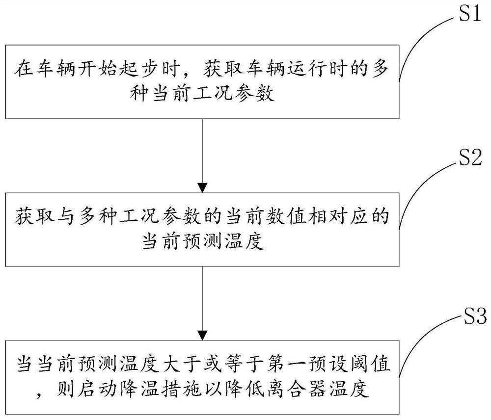
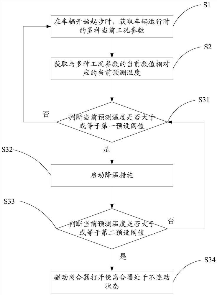
[0028] Such as figure 1 Distance figure 1 A flow chart showing a temperature control method of a double clutch transmission. This temperature control method includes the following steps:

[0029] S1: When the vehicle starts to start, a plurality of current working condition parameters at the time of the vehicle are obtained, and the process proceeds to step S2;

[0030] Vehicles include dual clutch transmission, engine, water-cooled heat dissipation system, and cooling fans. Double clutch transmission includes clutches and transmission. The clutch includes a power output and a power input. The power output of the clutch is connected to the transmission. The power input of the clutch is connected to the engine of the car. The clutch can pass the torque of the engine to the transmission when closed, and drive the transmission.

[0031] The water-cooled heat dissipation system is coupled to the double clutch transmission, the water-cooled heat dissipation system utilizes the heat of the


PUM


Abstract

A temperature control method for a dual-clutch transmission comprises the steps that when a vehicle starts to start, various current working condition parameters of the vehicle during running are obtained; according to the pre-calibrated corresponding relation between the various working condition parameters and the predicted temperature of the clutch, the current predicted temperature corresponding to the current numerical values of the various working condition parameters is obtained; and when the current predicted temperature is larger than or equal to the first preset threshold value, a cooling measure is started to reduce the clutch temperature. According to the method, the current preset temperature is predicted through the corresponding relation between the pre-calibrated various working condition parameters and the predicted temperature of the clutch, and if the current predicted temperature is larger than or equal to the first preset threshold value, the cooling measure is started for the clutch to reduce the temperature of the clutch. After the cooling measure is started, the highest temperature of the clutch in the starting process is lower than the current predicted temperature, and the possibility that the clutch is burnt down is reduced.

Description


Claims


Application Information

Patent Timeline
Owner ZHEJIANG GEELY HLDG GRP CO LTD
Why Eureka
Try Eureka