Stable wood planing assembly of a veneer wood planing machine

Inactive Publication Date: 2009-10-22
WANG YEN MING
View PDF4 Cites 11 Cited by
  • Summary
  • Abstract
  • Description
  • Claims
  • Application Information

AI Technical Summary

Benefits of technology

[0009]Therefore, it is a primary objective of the present invention to provide a stable planing assembly with a structure design that allows a material pressing component to be extended deeply to the contact point of the knife tool with the wood veneer to prevent the wood veneer from being pulled and shaken by the knife tool during a planing operation, so as to maintain a stable planing operation and a good planing quality.
[0010]Another objective of the present invention is to provide a stable planing assembly with a structural design that a material pressing structure can be adjusted appropriately to cope with the thickness and specification of the wood veneer to achieve the best pressing effect and maintain a stable and smooth planing operation.
[0011]To achieve the foregoing objectives, the structural design of the invention comprises a machine platform, a pair of parallel knife shafts disposed on the machine platform, a plurality of grooves disposed equidistantly on each knife shaft, and the grooves of the two knife shafts being arranged alternately with each other, such that knives between the two knife shafts can achieve a comprehensive planing operation of the

Problems solved by technology

However, most of such wood veneers are cut by a set of parallel saws at a time during the cutting process, and the two utmost external wood veneers and the middle wood veneer have a substantial error in thickness, and it is necessary to carry out an appropriate planing operation to assure a standard specification.
Although the structural design of such veneer wood planing machine can use the material pressing base to press the wood veneer appropriately, yet the material pressing base affects the planing operation of the knife tool,

Method used


Image

  • Stable wood planing assembly of a veneer wood planing machine
  • Stable wood planing assembly of a veneer wood planing machine
  • Stable wood planing assembly of a veneer wood planing machine

Examples


Embodiment Construction

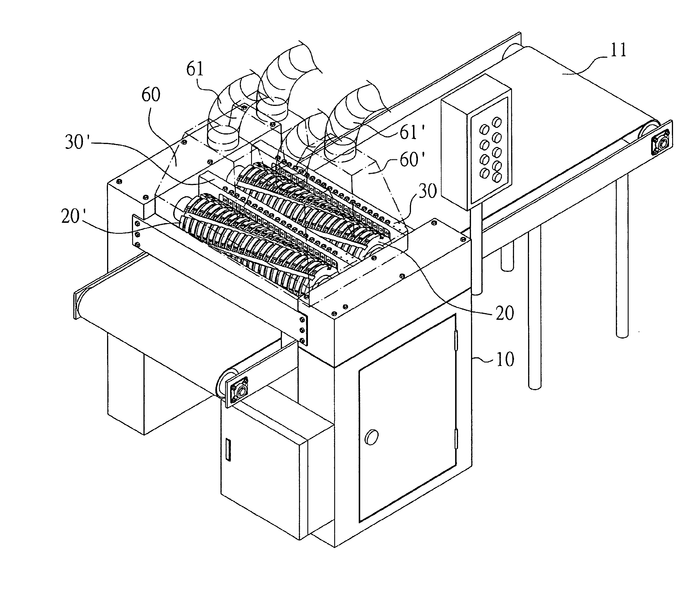
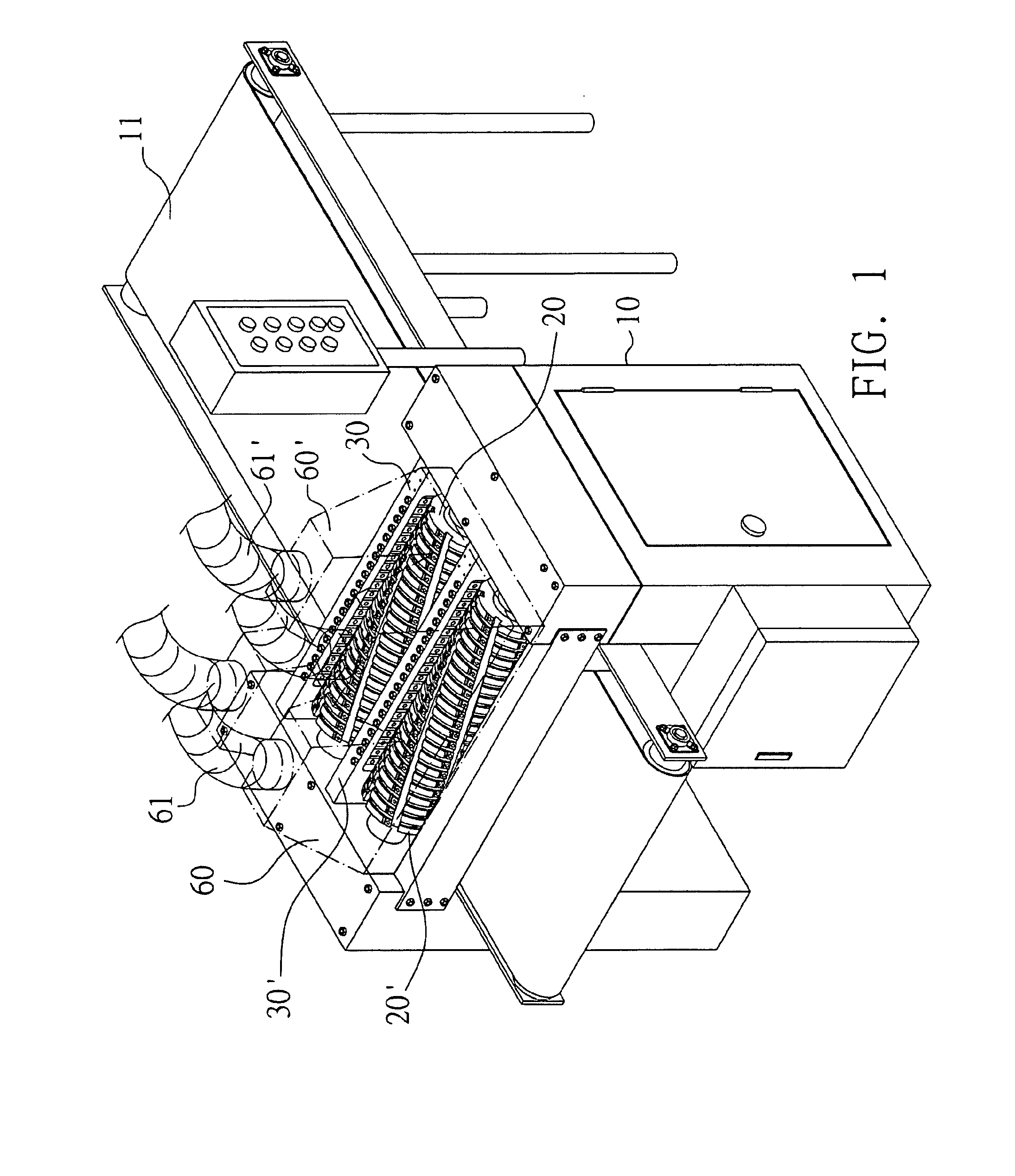
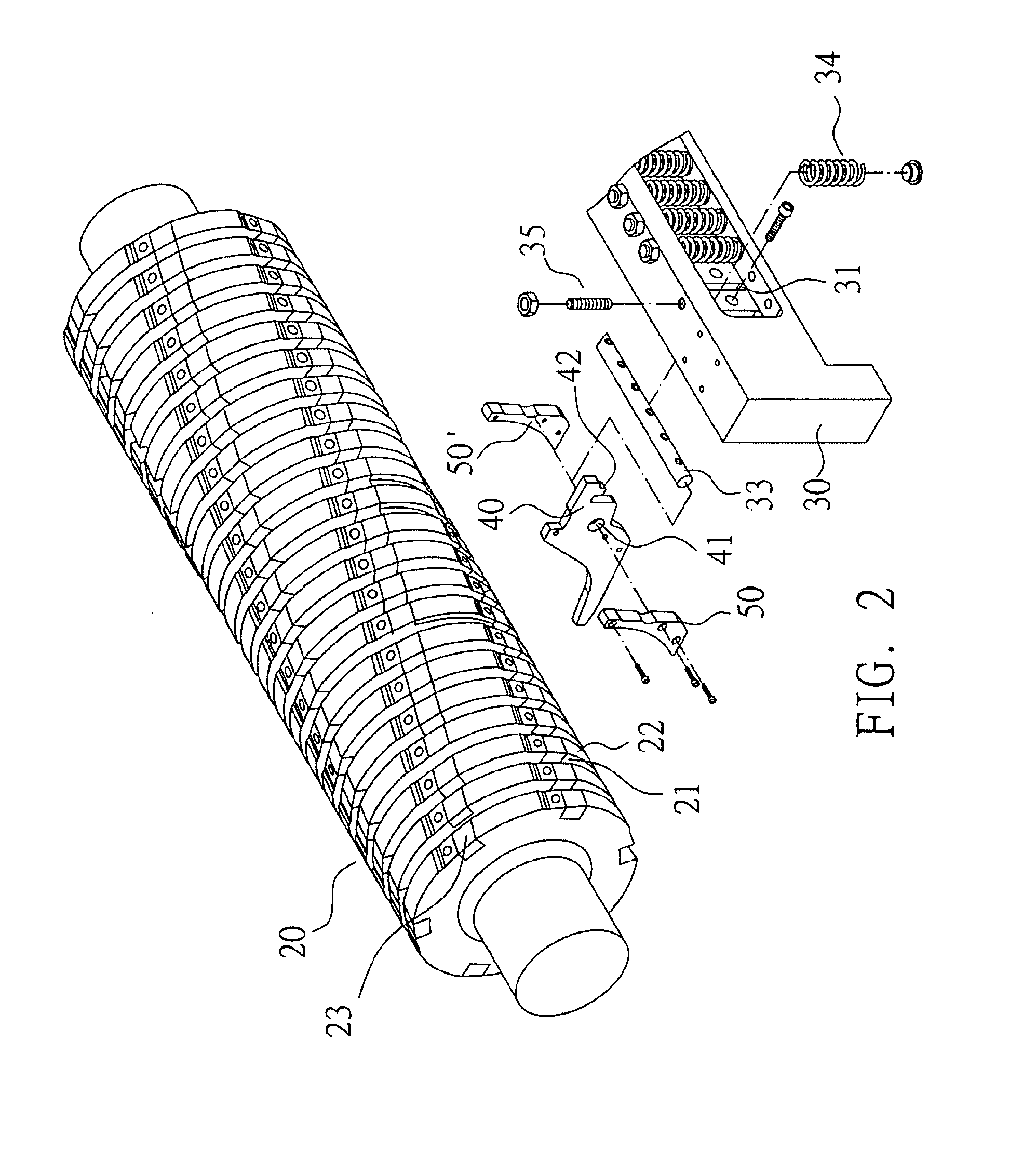
[0019]Referring to FIG. 1 for a perspective view of a structure of the invention, FIGS. 2 and 3 for exploded views of a structure and a portion of a structure of the invention respectively, and FIGS. 4 to 6 for views or a structure of the invention, a preferred embodiment of the invention comprises a machine platform 10, a pair of parallel knife shafts 20, 20′ disposed above the machine platform 10, a set of conveyor belt 11 passed below the pair of knife shafts 20, 20′ for conveying a wood veneer 1 placed on the conveyor belt 11 to the knife shafts 20, 20′, and carrying out a planing operation to a wood veneer 1 by using knife tools 23, 23′ installed on the knife shafts 20, 20′, a set of bases 30, 30′ disposed separately on a material feeding side of each knife shaft 20, 20′, a material pressing shoe 40, 40′ disposed separately at the bases 30, 30′ for pressing the wood veneer 1 appropriately to provide a stable planing operation, and a dust-collecting cover60, 60′ covered onto a spac


PUM


Abstract

The present invention discloses a stable wood planning assembly that can press and limit the wood veneer effectively to prevent the sharking during a planning operation. The assembly includes a pair of knife shafts having a base and a plurality of grooves disposed equidistantly from each other that the grooves of the two knife shafts are disposed alternately with each other. And the base includes a set of material pressing shoes installed axially and corresponds to a groove of the knife shaft, and the material pressing shoes has a curved surface corresponding to the groove of the knife shaft groove, at the rear end of the shoes has a spring that is used to stably press the wood veneer, and at both lateral sides of the shoes have a curvature bit guide plate which corresponds to the external diameter of the knife shaft, and a dust-collecting equipment attached.

Description


Claims


Application Information

Patent Timeline
Owner WANG YEN MING
Why Eureka
Try Eureka