LCD device based on dual source drivers with data writing synchronous control mechanism and related driving method

Inactive Publication Date: 2009-11-12
AU OPTRONICS CORP
View PDF13 Cites 15 Cited by
  • Summary
  • Abstract
  • Description
  • Claims
  • Application Information

AI Technical Summary

Benefits of technology

[0014]Furthermore, the present invention provides a driving method for driving a liquid crystal display device having a first source driver and a second source driver. The driving method comprises: furnishing a plurality of data signals to the first source driver and the second source driver; generating a plurality of first control signals by the first source driver, and generating a plurality of second control signals by the second source driver; performing a data-overwrite latching process on a plurality of odd-order data signals of the data signals based on the plurality of first control signals by the first source driver; performing a data-overwrite latching process on a plurality

Problems solved by technology

However, concerning an LCD device having high resolution, the width of each pixel unit is not enough for wiring a corresponding data line, and therefore two source drivers are required to be disposed on opposite sides of the LCD panel of the LCD device for coupling odd data lines and even data lines respectively.
However, as the resolution of the LCD panel is enhanced or the number of gray-scale levels of the image data signal is increased, the circuit design and layout of the data processing in

Method used


Image

  • LCD device based on dual source drivers with data writing synchronous control mechanism and related driving method
  • LCD device based on dual source drivers with data writing synchronous control mechanism and related driving method
  • LCD device based on dual source drivers with data writing synchronous control mechanism and related driving method

Examples


first embodiment

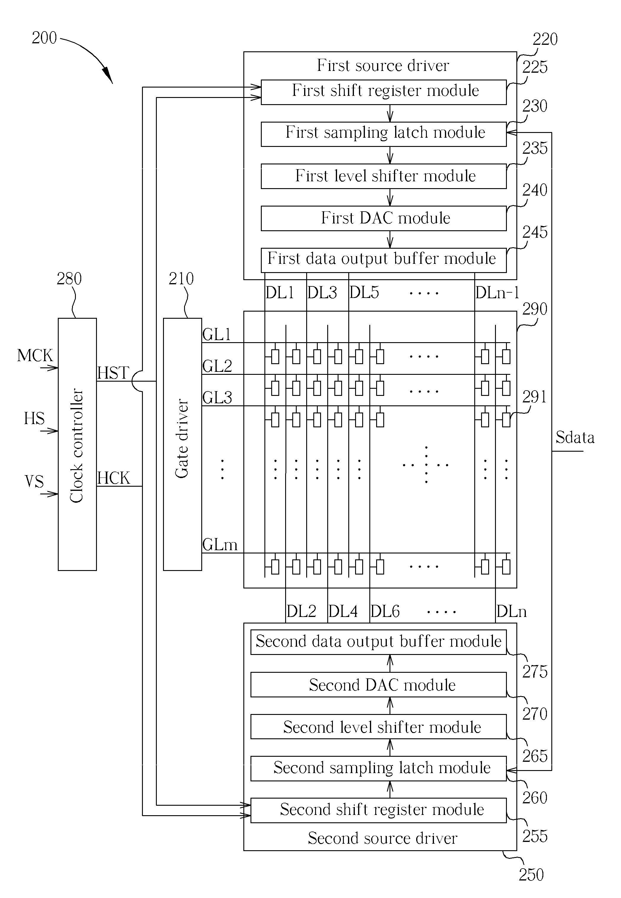
[0026]FIG. 2 is a schematic diagram showing an LCD device based on dual source drivers with data writing synchronous control mechanism in accordance with the present invention. As shown in FIG. 2, the LCD device 200 comprises a gate driver 210, a first source driver 220, a second source driver 250, a clock controller 280, an LCD panel 290, a plurality of gate lines GL1-GLm, and a plurality of data lines DL1-DLn. The clock controller 280 is utilized for generating a horizontal start signal HST and a horizontal clock signal HCK based on a master clock signal MCK, a horizontal synchronization signal HS, or a vertical synchronization signal VS. The first source driver 220 and the second source driver 250 are coupled to the clock controller 280 for receiving the horizontal start signal HST and the horizontal clock signal HCK. The LCD panel 290 comprises a plurality of pixel units 291. Each pixel unit 291 is coupled to a corresponding gate line and a corresponding data line.

[0027]The first s

second embodiment

[0042]FIG. 6 is a schematic diagram showing an LCD device based on dual source drivers with data writing synchronous control mechanism in accordance with the present invention. As shown in FIG. 6, the LCD device 600 comprises a gate driver 610, a first source driver 620, a second source driver 650, a clock controller 680, an LCD panel 690, a plurality of gate lines GL1-GLm, and a plurality of data lines DL1-DLn. The clock controller 680 is utilized for generating a first horizontal start signal HST1, a first horizontal clock signal HCK1, a second horizontal start signal HST2, and a second horizontal clock signal HCK2 based on a master clock signal MCK, a horizontal synchronization signal HS, or a vertical synchronization signal VS. The first source driver 620 is coupled to the first and second output ends of the clock controller 680 for receiving the first horizontal start signal HST1 and the first horizontal clock signal HCK1 respectively. The second source driver 650 is coupled to th


PUM


Abstract

An LCD device having dual source drivers and related driving method are disclosed for performing data signal driving operation by making use of a data writing synchronous control mechanism. The operation of the data writing synchronous control mechanism includes furnishing all image data signals to both the first and second source drivers, latching odd and even image data signals by the first and second source drivers respectively, performing a signal processing process on the odd image data signals for generating a first set of analog data signals by the first source driver, performing a signal processing process on the even image data signals for generating a second set of analog data signals by the second source driver, writing the first set of analog data signals into a plurality of first pixel units, and writing the second set of analog data signals into a plurality of second pixel units.

Description


Claims


Application Information

Patent Timeline
Owner AU OPTRONICS CORP
Why Eureka
Try Eureka