Load condition controlled power strip

a power strip and condition control technology, applied in the integration of power network operation systems, emergency power supply arrangements, relays, etc., can solve the problems of increasing the number of power loss, increasing the number of connected devices left on, and often going into self-imposed idle modes. , to achieve the effect of reducing or eliminating power, reducing the power consumption of the power strip, and facilitating the disengagement of the primary circui

Inactive Publication Date: 2009-12-31
IGO INC
View PDF76 Cites 43 Cited by
  • Summary
  • Abstract
  • Description
  • Claims
  • Application Information

AI Technical Summary

Benefits of technology

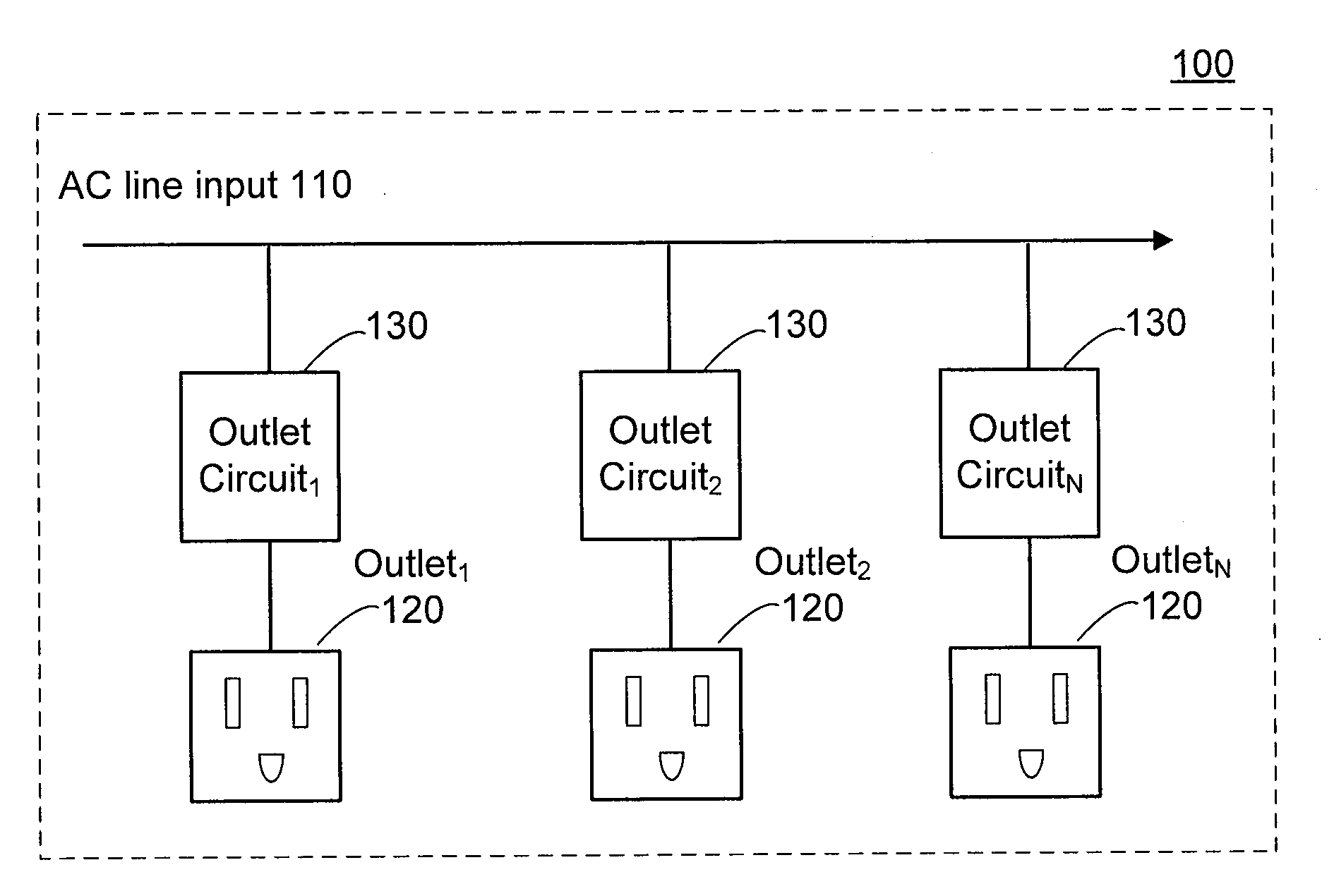
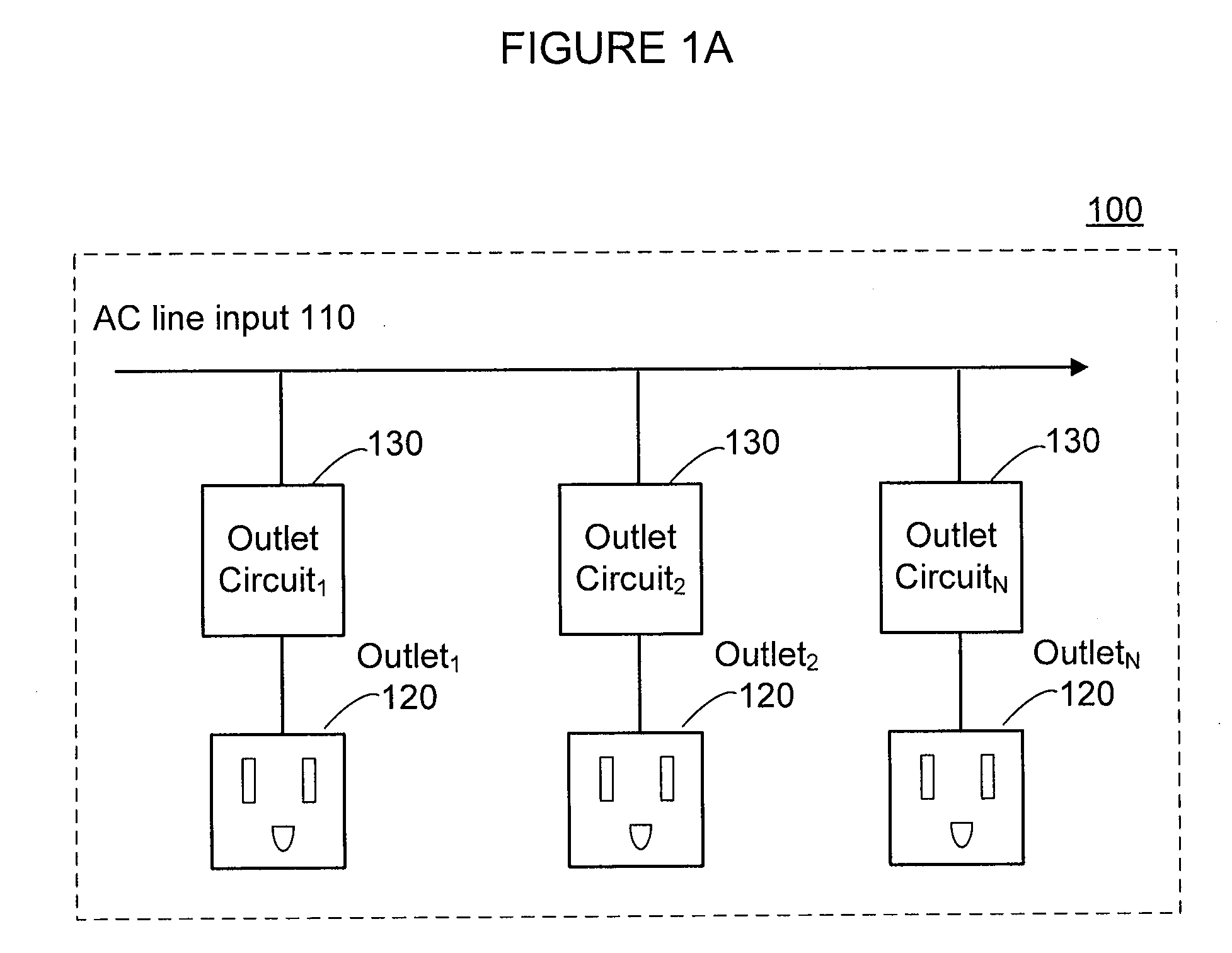
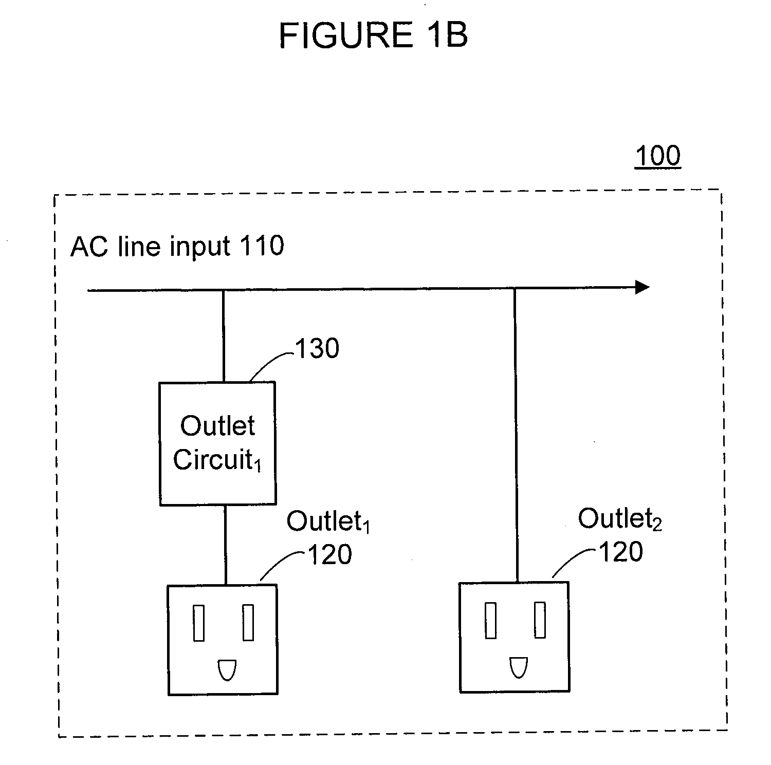
This patent describes a way to reduce energy usage when there's nothing going on while it's being used. It suggests using a power strip instead of just turning off all its power supply. When this happens, the power strip stops working properly but still has some power left over. To prevent this, the power strip can be designed to detect any activity near the end of each outlet. If only one outlet draws very little power, the power strip will automatically disable itself from doing useful work.

Problems solved by technology

The technical problem addressed in this patent text is how to reduce wasteful power usage while still maintaining environmental benefits. Power strips have been developed to help save power when not being used. However, current methods only work well for small devices like computers, monitors, printers, scanners, etc., but they cannot accurately detect idle states of individual outlets without having to constantly check them manually.

Method used


Image

  • Load condition controlled power strip
  • Load condition controlled power strip
  • Load condition controlled power strip

Examples


Embodiment Construction

[0013]The present invention may be described herein in terms of various functional components and various processing steps. It should be appreciated that such functional components may be realized by any number of hardware or structural components configured to perform the specified functions. For example, the present invention may employ various integrated components, such as buffers, current mirrors, and logic devices comprised of various electrical devices, e.g., resistors, transistors, capacitors, diodes and the like, whose values may be suitably configured for various intended purposes. In addition, the present invention may be practiced in any integrated circuit application. However for purposes of illustration only, exemplary embodiments of the present invention will be described herein in connection with a sensing and control system and method for use with power strip circuits. Further, it should be noted that while various components may be suitably coupled or connected to oth


PUM


Abstract

In accordance with various aspects of the present invention, a method and circuit for reducing power consumption of a power strip is provided. In an exemplary embodiment, a power strip is configured for reducing or eliminating power during idle mode by disengaging an outlet from power input. A power strip may include two or more outlets and two or more outlet circuits, with AC power input connected to the outlets through the outlet circuit(s), which may include a current transformer, a control circuit, and a switch. The current transformer secondary winding provides an output power level signal proportional to the outlet load. If behavior of the current transformer secondary winding indicates that the outlet is drawing substantially no power from the AC power input, the switch facilitates disengaging of the current transformer primary from the outlet.

Description


Claims


Application Information

Patent Timeline
Owner IGO INC
Why Eureka
Try Eureka