Flashlight

Inactive Publication Date: 2010-02-11
LIU YUN ZHAO
View PDF6 Cites 2 Cited by
  • Summary
  • Abstract
  • Description
  • Claims
  • Application Information

AI Technical Summary

Benefits of technology

[0007]A flashlight in accordance with an embodiment of the present invention includes a lamp support, an electric light-generating mechanism in the lamp support, a covering member around the lamp support, a barrel body joined on the covering member, a power supply held in the barrel body, and an adjustment member. The adjustment member is threadedly joined in the lamp support, and can be turned to adjust a position of a focal point of light emitted from a light source of the light-generating mechanism. Front and rear heat-conducting compo

Problems solved by technology

However, the high-power light emitting diodes will produce a large amount of waste heat when they are shining.
The light emitting diodes will become very hot and less efficient, and can even get damaged

Method used


Image

  • Flashlight
  • Flashlight
  • Flashlight

Examples


Embodiment Construction

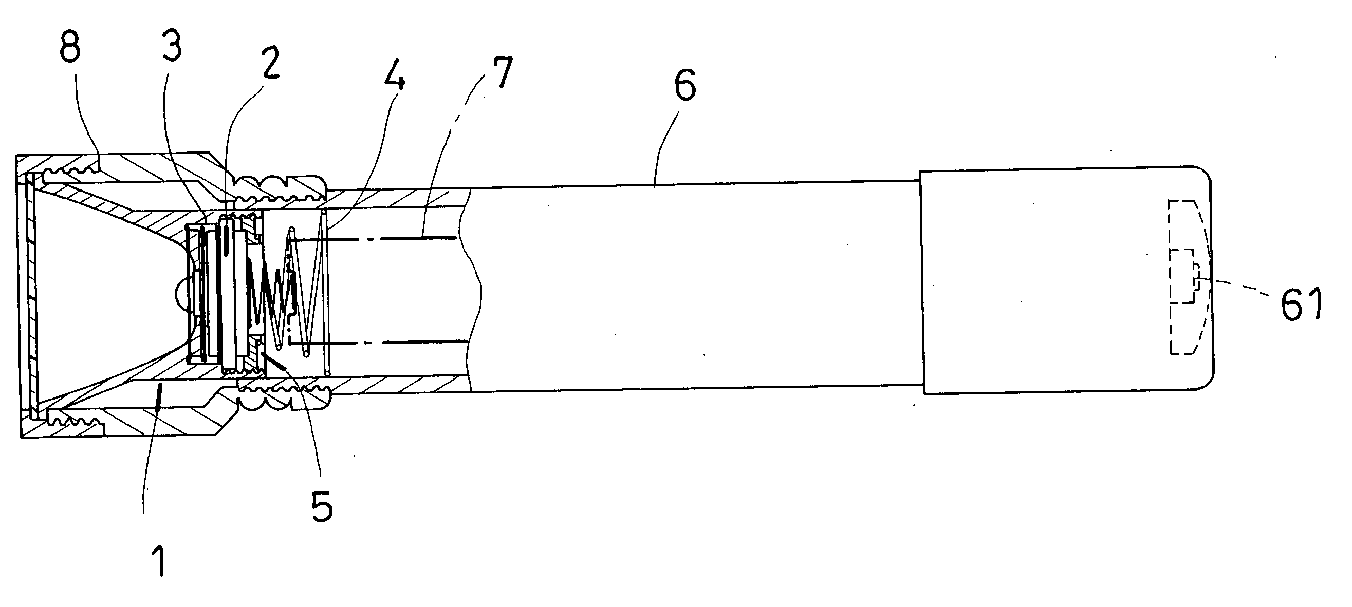
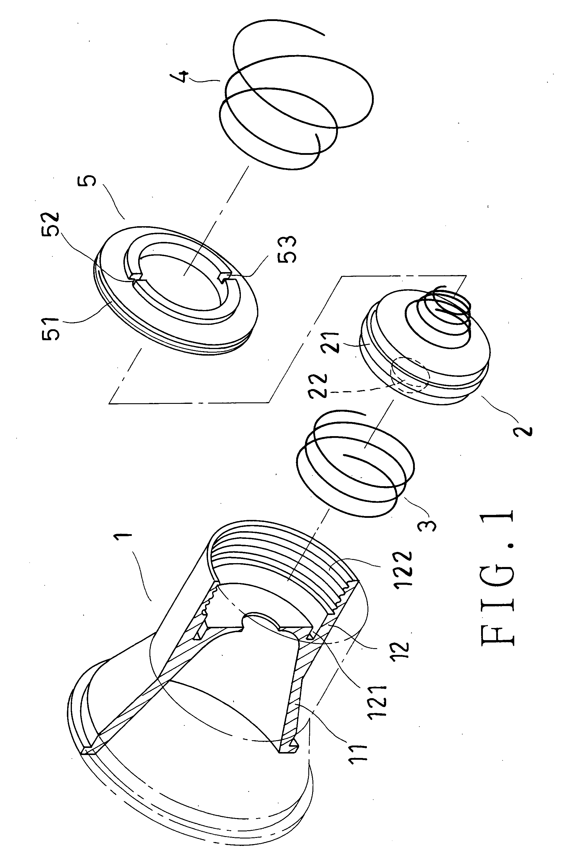
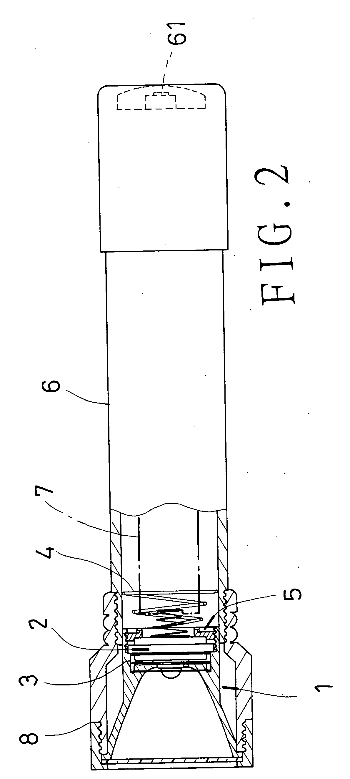
[0013]Referring to FIG. 1 to FIG. 3, preferred embodiment of a flashlight of the present invention includes a lamp support 1, an electric light generating mechanism 2, a front heat-conducting component 3, a rear heat-conducting component 4, an adjustment member 5 for adjusting a position of a focal point of light emitted from a light source, a barrel body 6, a power supplying mechanism 7, and a covering member 8.

[0014]The lamp support 1 has a light-reflecting cup 11, and a joining part 12; the light-reflecting cup 11 is substantially in the shape of a horn, and adjoins a front end of the joining part 12, and it further communicates with the joining part 12; the joining part 12 has a threaded portion 122 on a rear end thereof, and a locating groove 121 on the front end.

[0015]The electric light-generating mechanism 2 is held in the joining part 12 of the lamp support 1, and includes a circuit board 21, and a light source 22 joined on the circuit board 21; the circuit board 21 has a contr


PUM


Abstract

A flashlight includes a lamp support, an electric light-generating mechanism in the lamp support, a covering member around the lamp support, a barrel body joined on the covering member, and an adjustment member; the adjustment member is threadedly joined in the lamp support, and can be turned to adjust a position of a focal point of light emitted from a light source of the light-generating mechanism; front and rear heat-conducting components are positioned on front and rear ends of the light-generating mechanism respectively, and they contact the lamp support and the barrel body respectively; heat produced from functioning of the light-generating mechanism will be conducted away from the front heat-conducting component to the lamp support and from the rear heat-conducting component to the barrel body, and the light source is prevented from being damaged by the heat produced from it continuing shining for an extended length of time.

Description


Claims


Application Information

Patent Timeline
Owner LIU YUN ZHAO
Why Eureka
Try Eureka