In-cabinet thermal monitoring method and system

a thermal monitoring and in-cabinet technology, applied in the field of thermal monitoring of electrical equipment, can solve the problems of requiring a trained operator, requiring a large number of thermographic imaging limitations, and a large number of equipment limitations

Active Publication Date: 2010-02-25
ROCKWELL AUTOMATION TECH
View PDF9 Cites 27 Cited by
  • Summary
  • Abstract
  • Description
  • Claims
  • Application Information

AI Technical Summary

Benefits of technology

In this new technology, there are two technical features: one being able to monitor multiple points at once without having permanent installations like traditional temperature sensors or infrared imaging devices; another being capable of automatically tracking changes over time based on external factors such as ambient temperatures or other environmental variables. These technologies can help reduce costs while still providing accurate results compared with current methods requiring expensive sensor installation.

Problems solved by technology

This patented describes an improved way to automatically detect and manage temperature on electric machines during their lifetime. It involves utilizing special techniques like camera technology to capture heat from different parts inside the machine's housing. By analyzing this captured heat, it becomes possible to identify issues early before any damage occurs due to improper use or malfunctions. Additionally, there has been developed methods for continuously monitoring these systems through infra red light transmission windows or opaque doors.

Method used


Image

  • In-cabinet thermal monitoring method and system
  • In-cabinet thermal monitoring method and system
  • In-cabinet thermal monitoring method and system

Examples


Embodiment Construction

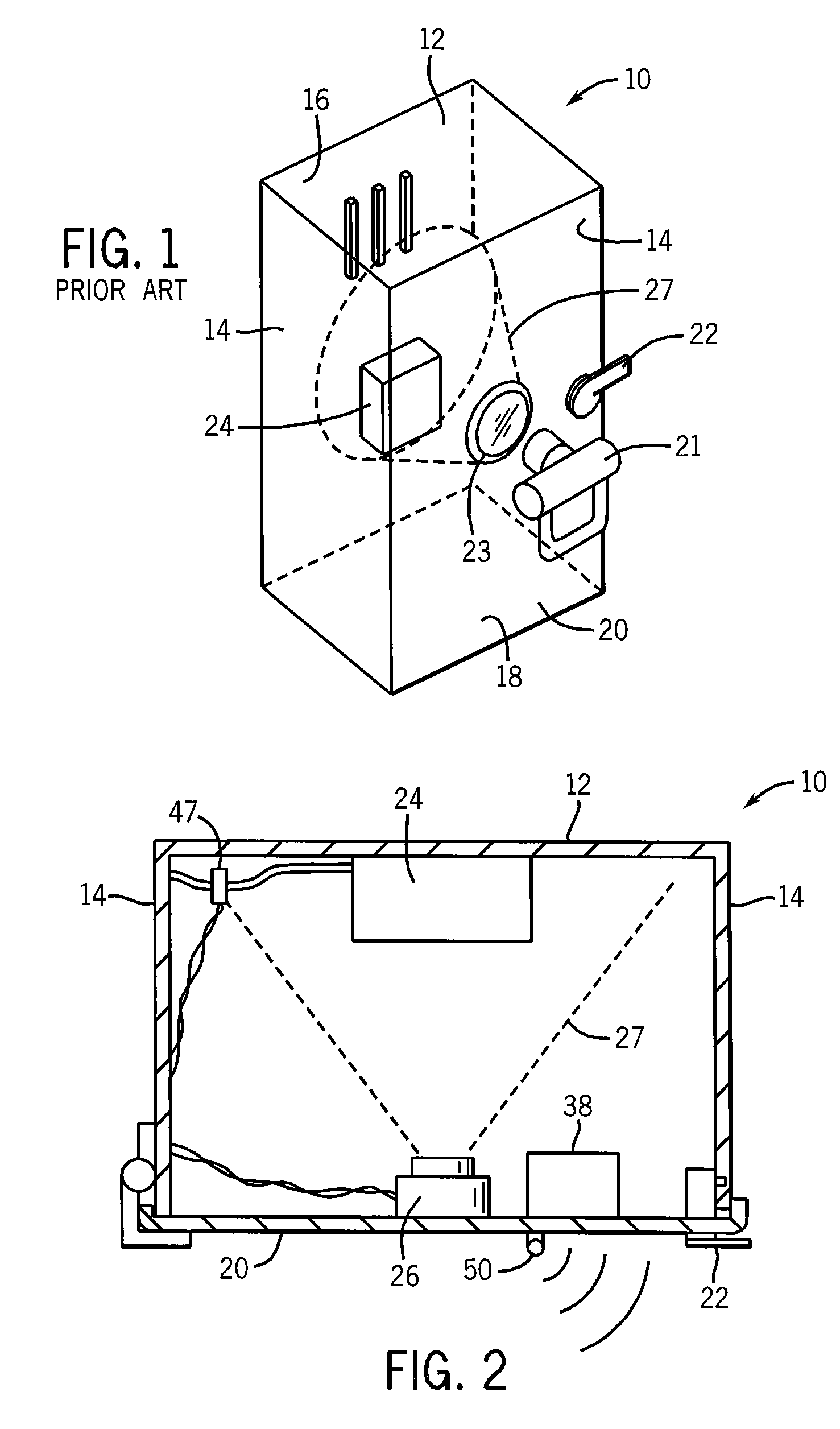
[0042]Referring now to FIG. 1, a switchgear cabinet 10 may have a rear vertical wall providing a mounting panel 12 surrounded by forwardly extending sidewalls 14, top wall 16 and bottom wall 18 to provide a protected volume enclosed by front door 20 opposite the mounting panel 12. Typically the cabinet 10 is constructed of steel panels to provide a strong and fire resistant housing.

[0043]The front door 20 may be opened and closed for access to the enclosed volume in the cabinet 10 by means of a handle 22 which may turn to lock the cabinet 10 and which may be connected to an electrical interlock (not shown) or the like to disconnect power from the cabinet 10 when the door 20 is opened. The door 20 may support a port 23 providing either an infrared transparent window or an openable shutter allowing viewing of internal components by a thermographic camera 21 by a human operator while providing maximum protection to the operator.

[0044]The cabinet 10 may include multiple electrical componen


PUM


Abstract

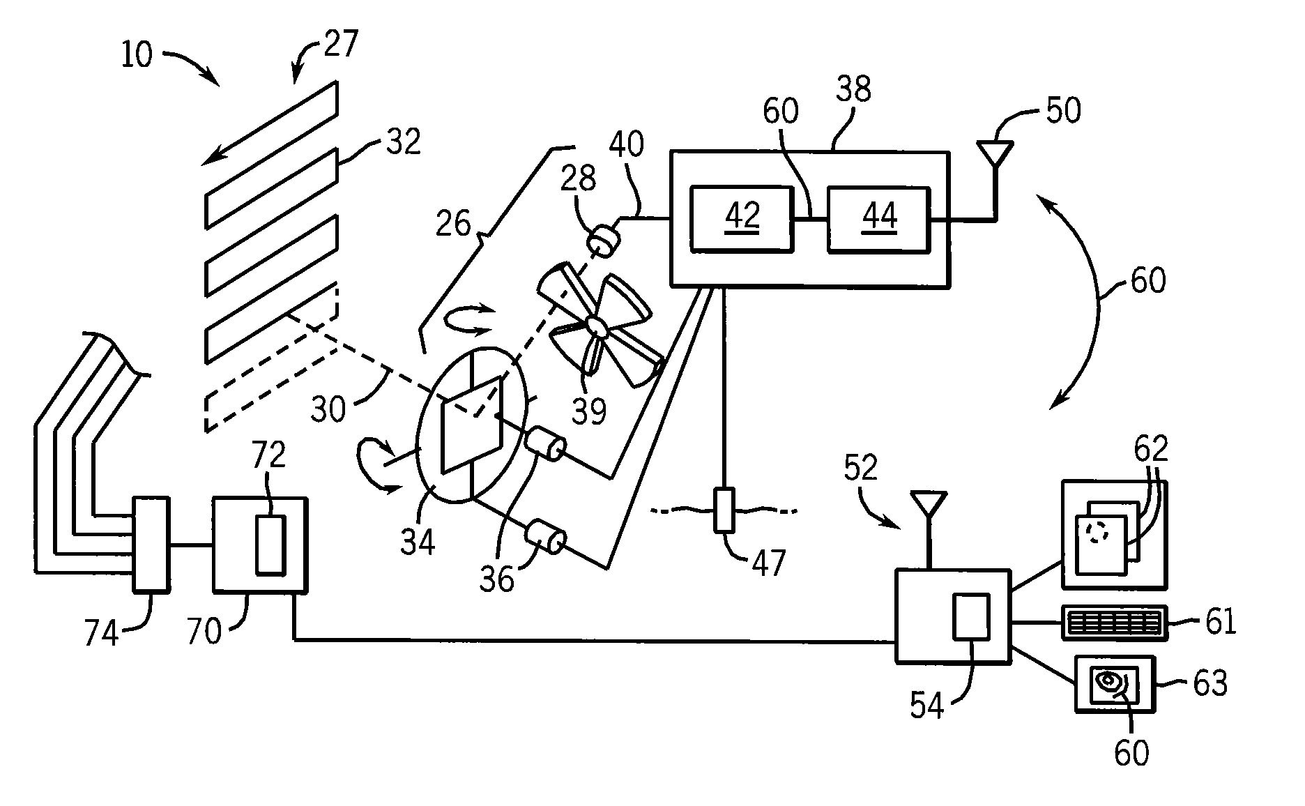
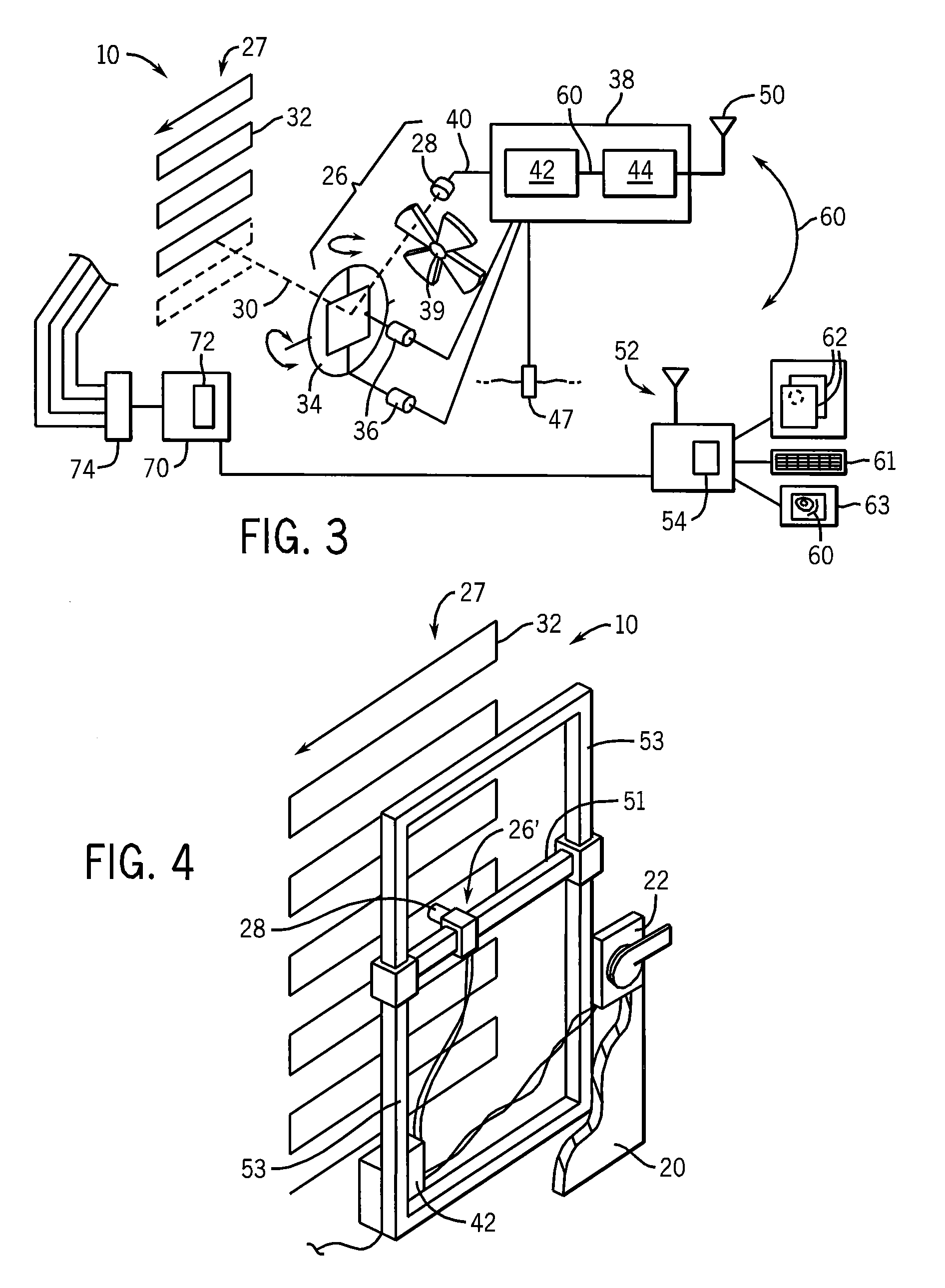
Thermographic imaging equipment is incorporated directly into cabinets housing electrical switchgear to provide for dedicated, nearly continuous monitoring of the contained equipment. A mechanical scanning technique may allow low-cost sensors to provide essentially continuous thermographic monitoring. Dedicated thermal imaging equipment allows automatic analysis through predefined temperature threshold maps.

Description


Claims


Application Information

Patent Timeline
Owner ROCKWELL AUTOMATION TECH
Why Eureka
Try Eureka