Receiver device, transmission system, and packet transmission method
a transmission system and receiver technology, applied in the field of transmission systems, can solve the problems of frequent packet loss, poor communication quality, flickering or accidental interruption of tv broadcast video during broadcasting,
- Summary
- Abstract
- Description
- Claims
- Application Information
AI Technical Summary
Benefits of technology
Problems solved by technology
Method used
Image

Examples
first embodiment
A. First Embodiment
A-1. Configuration of First Embodiment
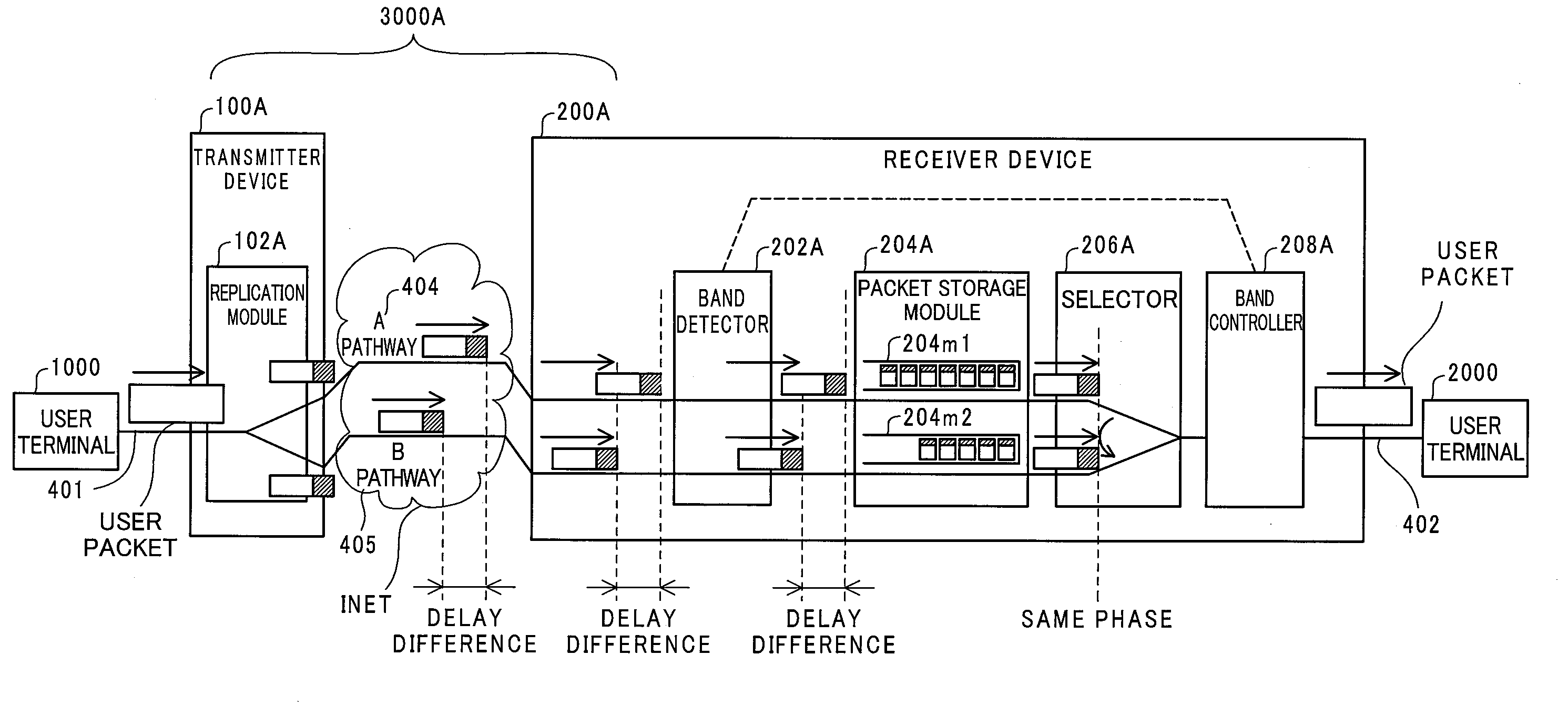
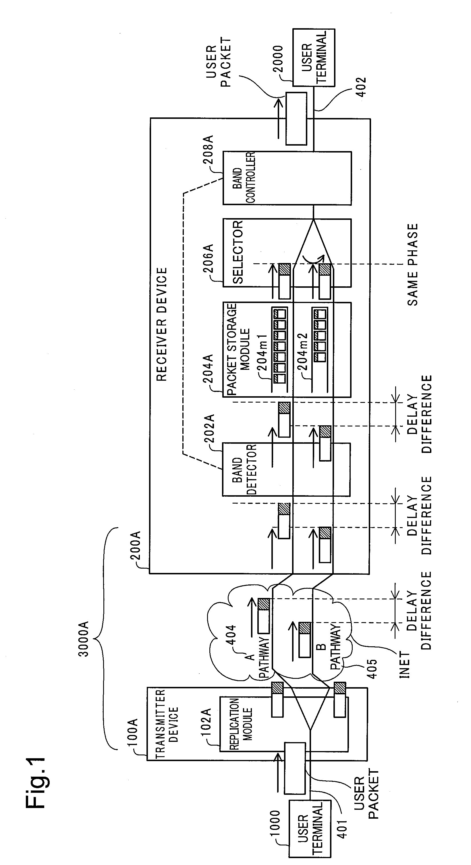
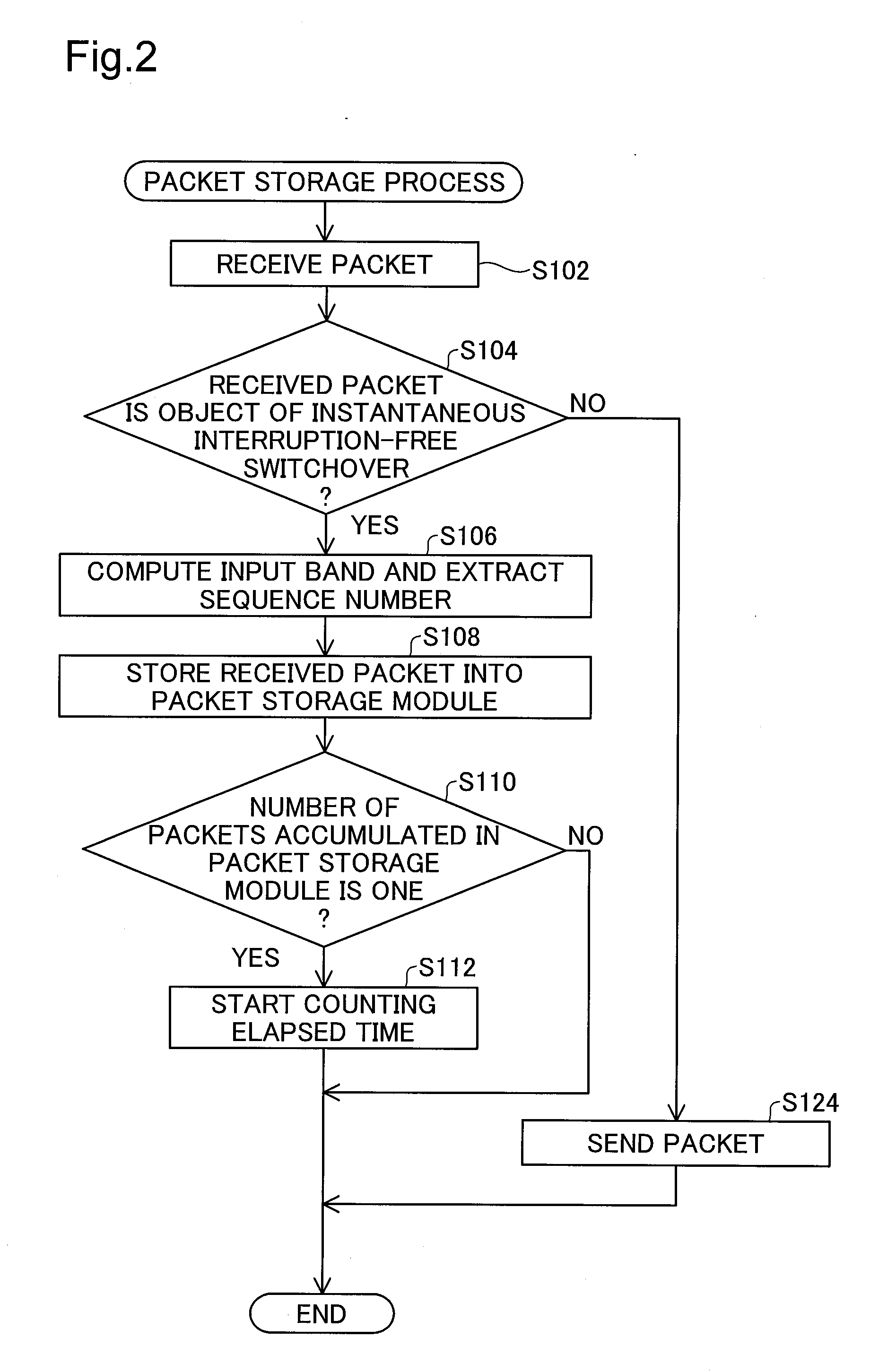
[0045]A first embodiment of the present invention is described below. FIG. 1 illustrates the configuration of a transmission system 3000A in the first embodiment of the invention. The transmission system 3000A is located between a user terminal 1000 and another user terminal 2000 interconnected via the Internet. On the occurrence of some fault or trouble in any pathway of the Internet, the transmission system 3000A allows packets sequentially input from the user terminal 1000 to reliably reach the user terminal 2000 without causing any instantaneous interruption, that is, in an ‘instantaneous interruption-free’ manner. A switchover of a transmission path without causing any packet missing is referred to as ‘instantaneous interruption-free switchover’ in the specification hereof. As described later, each of the packets received by the transmission system 3000A is identified as a preset object or non-object of instantaneous interru
second embodiment
B. Second Embodiment
B-1. Configuration of Second Embodiment
[0096]A second embodiment of the present invention is described below. FIG. 7 illustrates the configuration of a transmission system 3000B in the second embodiment of the invention. Like the transmission system 3000A of the first embodiment, the transmission system 3000B of the second embodiment is located between a user terminal 1000 and another user terminal 2000 interconnected via the Internet. As illustrated, the transmission system 3000B of the second embodiment has a transmitter device 100B and a receiver device 200B, similar to the transmission system 3000A of the first embodiment. The difference of the transmission system 3000B of the second embodiment from the transmission system 3000A of the first embodiment is that the input band of each user packet is computed by the transmitter device 100B, in place of the receiver device 200B. Such modification desirably relieves the processing load of the receiver device 200B. Th
third embodiment
C. Third Embodiment
C-1. Configuration of Third Embodiment
[0135]A third embodiment of the present invention is described below. FIG. 13 illustrates the configuration of a transmission system 3000C in the third embodiment of the invention. Like the transmission system 3000A of the first embodiment, the transmission system 3000C of the third embodiment is located between a user terminal 1000 and another user terminal 2000 interconnected via the Internet. As illustrated, the transmission system 3000C of the third embodiment has a transmitter device 100C and a receiver device 200C, similar to the transmission system 3000A of the first embodiment. The difference of the transmission system 3000C of the third embodiment from the transmission system 3000A of the first embodiment is that the band detector 202A and the band controller 208A included in the receiver device 200A are replaced by a time monitor 212C included in the receiver device 200C. The like constituents of the third embodiment to
PUM
 Abstract
Description
Claims
Application Information
 - R&D Engineer
- R&D Manager
- IP Professional
- Industry Leading Data Capabilities
- Powerful AI technology
- Patent DNA Extraction
Browse by: Latest US Patents, China's latest patents, Technical Efficacy Thesaurus, Application Domain, Technology Topic.
© 2024 PatSnap. All rights reserved.Legal|Privacy policy|Modern Slavery Act Transparency Statement|Sitemap