Tilt Device for a Material Handling Machine

Active Publication Date: 2010-10-21
TIMBERPRO
View PDF84 Cites 11 Cited by
  • Summary
  • Abstract
  • Description
  • Claims
  • Application Information

AI Technical Summary

Benefits of technology

[0007]The cab and the boom assembly are rotatable about a turntable axis that is perpendicular to and intermediate the first and second pivot axes. Furthermore, the turntable axis is intermediate the first and second spindles. Thus, by rotating the mounting plate and moving the rams, the boom and the cab can be adjusted in response to the working surface and the working environment to be in the most appropriate orientation and the most appropriate tilt state for handling material. Thus, the machine according to the preferred teachings of the present invention does not use the expensive circular base of conventional apparatuses and, thus, has reduced overall height and hence less limitation to passing under a bridge or restricted space. Furthermore, the machine according to the preferred teachings of the present invention allows easy access to the frame and the components connected thereto for maintenance without adversely affecting 360° rotation and tilt of the

Problems solved by technology

However, even such excellent devices have experienced some limitations for which further improvement was needed.
The overall height of the apparatus is relatively high and, thus, results

Method used


Image

  • Tilt Device for a Material Handling Machine
  • Tilt Device for a Material Handling Machine
  • Tilt Device for a Material Handling Machine

Examples


Embodiment Construction

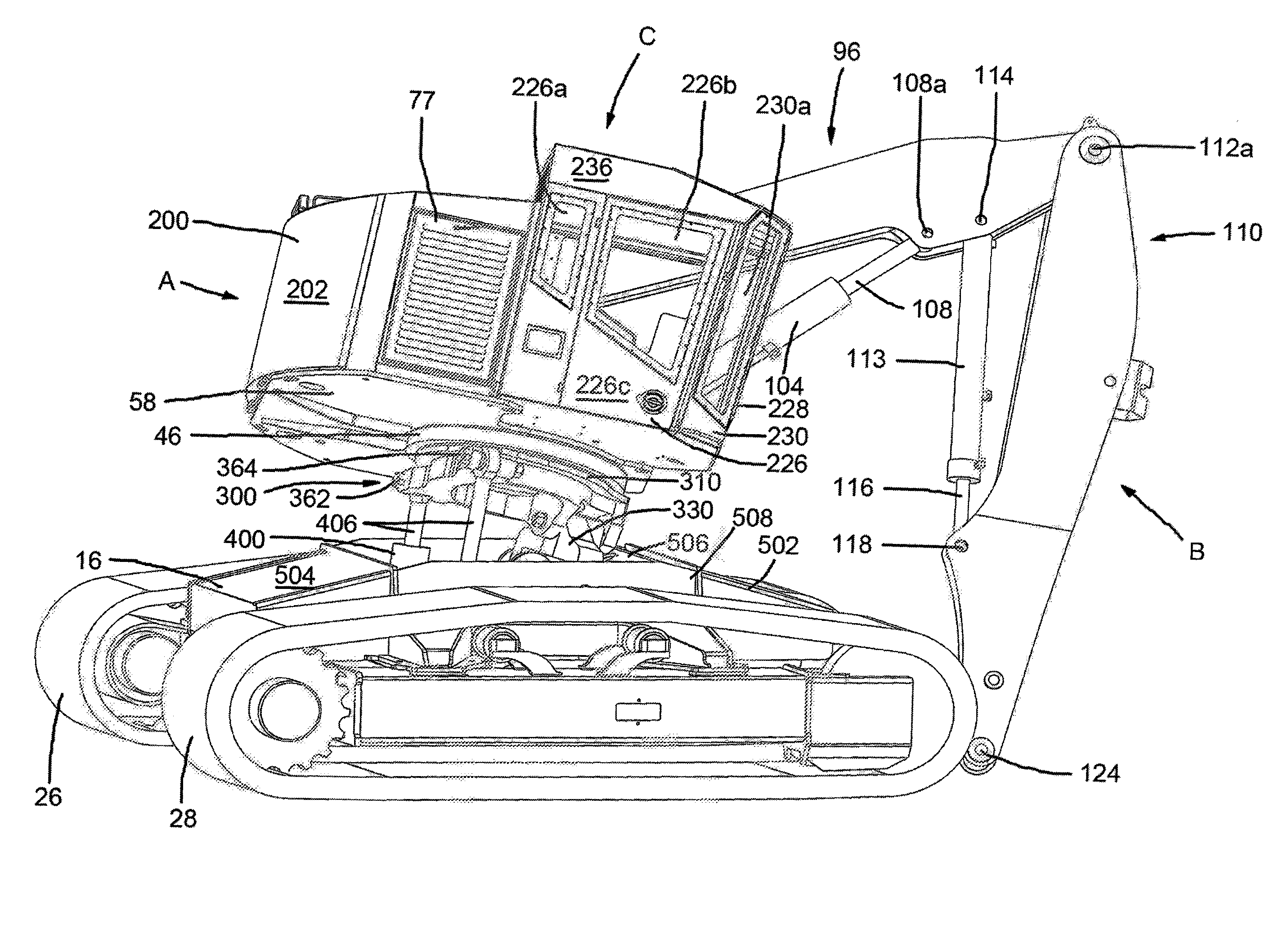
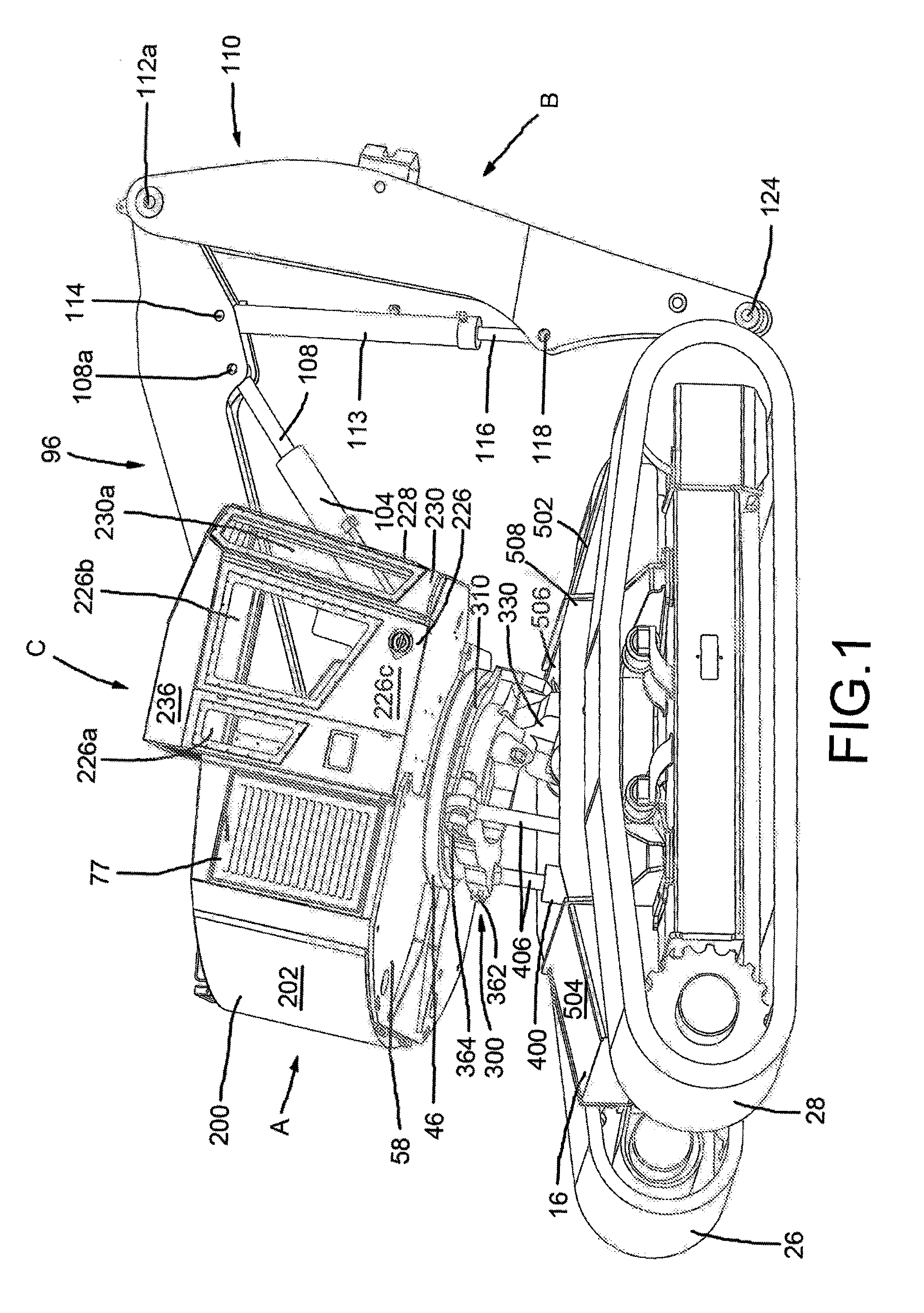
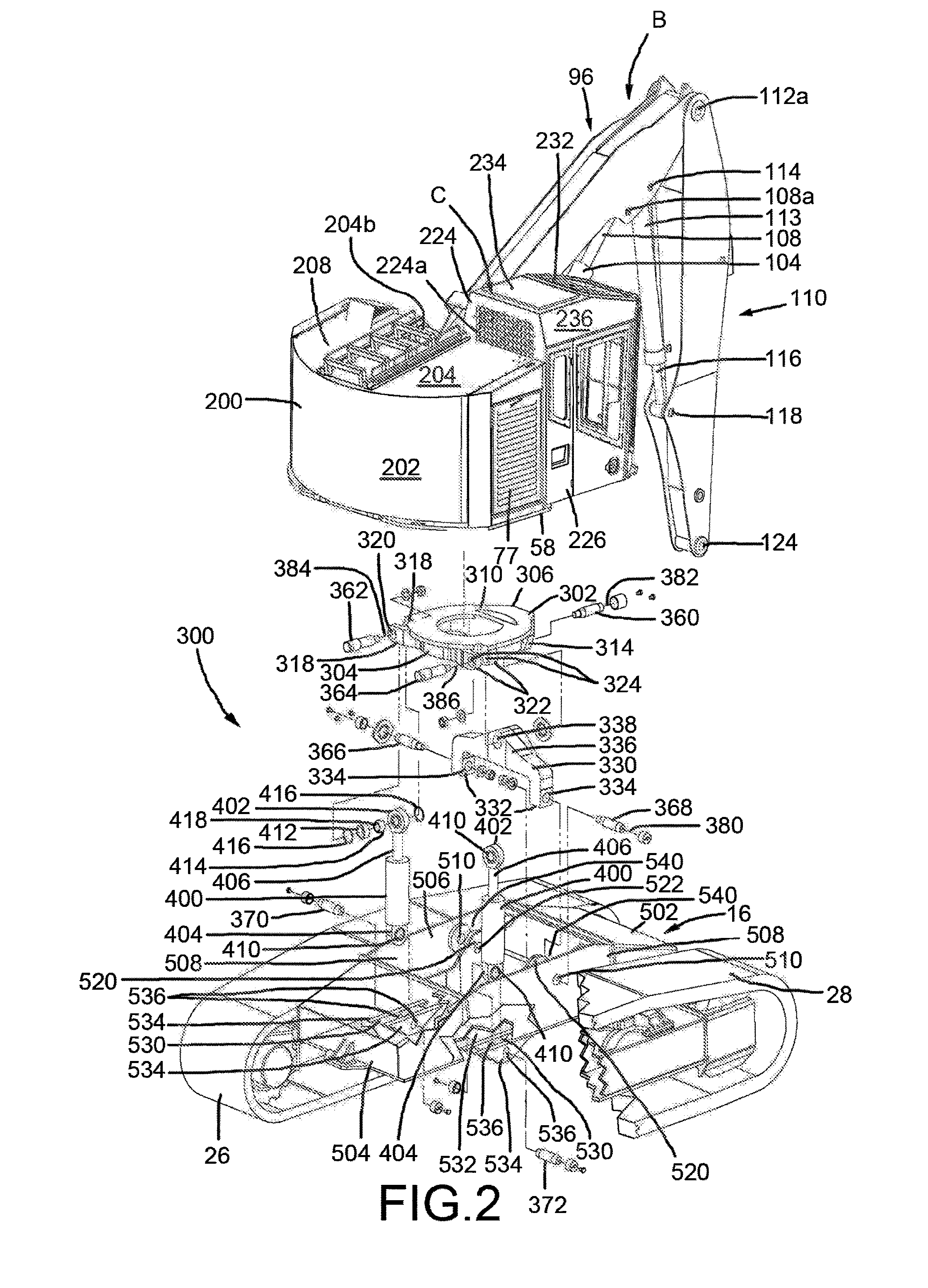
[0016]A material handling machine according to the preferred teachings of the present invention is shown in the drawings and generally designated A. Machine A can be utilized to handle materials including but not limited to fell and handle trees. Generally, machine A includes a longitudinally extending frame 16 having a front end 502, a rear end 504, and a compartment 506 between front and rear ends 502 and 504. In the preferred form shown, frame 16 includes two parallel, spaced lateral walls 508 parallel to the longitudinal direction of frame 16 between front and rear ends 502 and 504 and defining the compartment 506. Lateral walls 508 include aligned pin holes 510 in front portions thereof adjacent to front end 502.

[0017]Two plates 520 are mounted in the compartment 506 on a bottom plate 532 and parallel to and spaced from lateral walls 508 by spacings 540. Plates 520 include pin holes 522 aligned with pin holes 510 of lateral walls 508. Two aligned grooves 530 are defined in a rear


PUM


Abstract

A machine (A) includes a frame (16) and a platform (58) on which a boom assembly (B) is mounted. Two arms (332) of a U-shaped pivotal member (330) are pivotably mounted to the frame (16) about a first pivot axis (380) perpendicular to a longitudinal direction of the frame (16). A front end (302) of a mounting plate (310) is pivotably connected to an intermediate section (336) of the pivotal member (330) about a second pivot axis (382) perpendicular to and spaced from the pivot axis (380). Two rams (400) are mounted on opposite sides of a rear end (304) of the mounting plate (310). Each ram (400) includes a lower end (404) pivotably connected to the frame (16) and an upper end (402) pivotably connected to one of the sides of the mounting plate (310). The boom assembly (B), the mounting plate (310), and the pivotal member (330) pivot about the first pivot axis (380) and/or the second pivot axis (382) relative to the frame (16) due to relative movement of the rams (400).

Description


Claims


Application Information

Patent Timeline
Owner TIMBERPRO
Why Eureka
Try Eureka