System for attenuating pulsation in the gas discharge of a refrigeration compressor

Inactive Publication Date: 2010-12-09
WHIRPOOL SA
View PDF6 Cites 19 Cited by
  • Summary
  • Abstract
  • Description
  • Claims
  • Application Information

AI Technical Summary

Benefits of technology

[0005]It is a generic object of the present invention to provide a system for attenuating pulsation in the gas discharge of a refrigeration compressor, par

Problems solved by technology

The pulsation of the gases generates an excitation in the ducts and components to which the discharge of the compressor is coupled, which in turn generates noise.
Although this discharge system solution presenting a configuration of volumes “in se

Method used


Image

  • System for attenuating pulsation in the gas discharge of a refrigeration compressor
  • System for attenuating pulsation in the gas discharge of a refrigeration compressor
  • System for attenuating pulsation in the gas discharge of a refrigeration compressor

Examples


Embodiment Construction

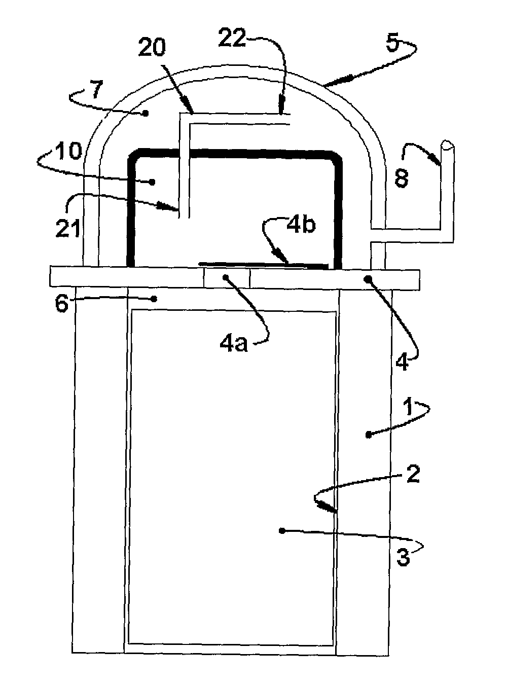
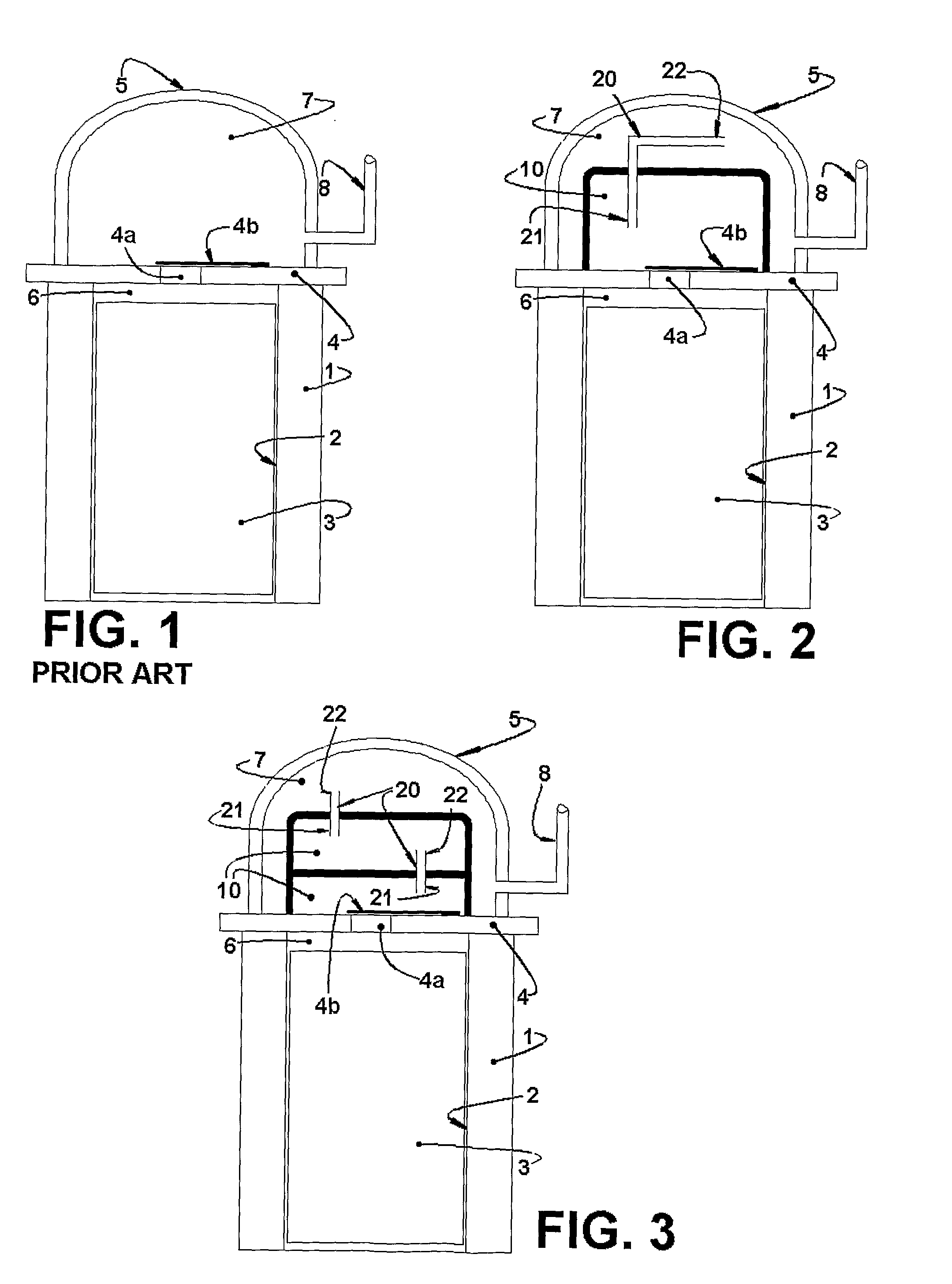
[0015]The present invention will be described for a reciprocating hermetic compressor which comprises a motor-compressor assembly having a cylinder block 1, which defines a cylinder 2, inside which a piston 3 is axially displaced by actuation of a motor (not illustrated). In a particular compressor construction of the type driven by a linear motor, the piston 3 is connected to a resonant spring (not illustrated) and axially displaced in the interior of the cylinder 2 by an actuating assembly (not illustrated), which supports a magnetic component (not illustrated) and which is axially driven upon energization of the linear motor.

[0016]The cylinder 2 has an open end, through which the piston 3 is housed, and an opposite end closed by a valve plate 4, against which is seated a cylinder cover 5. The valve plate 4 carries at least one of the suction valve and discharge valve, which regulate the gas inlet and outlet in relation to the interior of the cylinder 2. In the illustrated constructi


PUM


Abstract

The attenuation system is applied to a compressor which comprises: a cylinder (2) having an end closed by a valve plate (4) provided with a discharge orifice (4a) and defining, with the cylinder (2), a compression chamber (6), a cylinder cover (5) being seated against the valve plate (4) and defining a discharge chamber (7), which communicates with the exterior of the compressor through a discharge tube (8). The attenuation system comprises: at least one intermediary chamber (10) defined in the interior of the discharge chamber (7), in order to receive, from the discharge orifice (4a), the whole discharge flow coming from the compression chamber (6); and at least one 4a connecting tube (20) mounted in the interior 4b of the discharge chamber (7), having a first end (21) open to the interior of the intermediary chamber (10) and a second end (22) open to the interior of the discharge chamber (7).

Description


Claims


Application Information

Patent Timeline
Owner WHIRPOOL SA
Why Eureka
Try Eureka