Fire protection device

Inactive Publication Date: 2010-12-30
HILTI AG
View PDF9 Cites 11 Cited by
  • Summary
  • Abstract
  • Description
  • Claims
  • Application Information

AI Technical Summary

Benefits of technology

[0012]In the insertion position of the second attachment device, the fire protection device can be easily inserted into the opening, e.g., by being pushed. When the second attachment device is displaced in its attachment position, e.g., by tightening the first attachment device, the fire protection device is easily secured in the constructional component. In one operational step or mounting step, the necessary fire proofing for the leadthrough is provided. The inventive fire protection device, contrary to the device according to DE 90 11 954 U, is secured in the constructional component at two, axially spaced from each other, regions.
[0029]Advantageously, a free end of the at least one attachment section faces in direction of the first attachment device in an insertion position of the second attachment device. Thereby, in particular, upon an axial displacement of the second attachment device in the direction of the first attachment device, hooking of the free ends of the at least one attachment section, e.g., in the wall of the opening in the constructional component, or engagement of an end of the opening is insured in a simple manner.

Problems solved by technology

The drawback of the known device consists in that the outer dimensions of the housing must be adapted to the inner dimensions of the opening in the constructional component in order, e.g., to prevent tilting of the fire protection device in the opening upon passing of a conduit through.
This requires large logistic expenses by both the manufacturer and the user.

Method used


Image

  • Fire protection device
  • Fire protection device
  • Fire protection device

Examples


Embodiment Construction

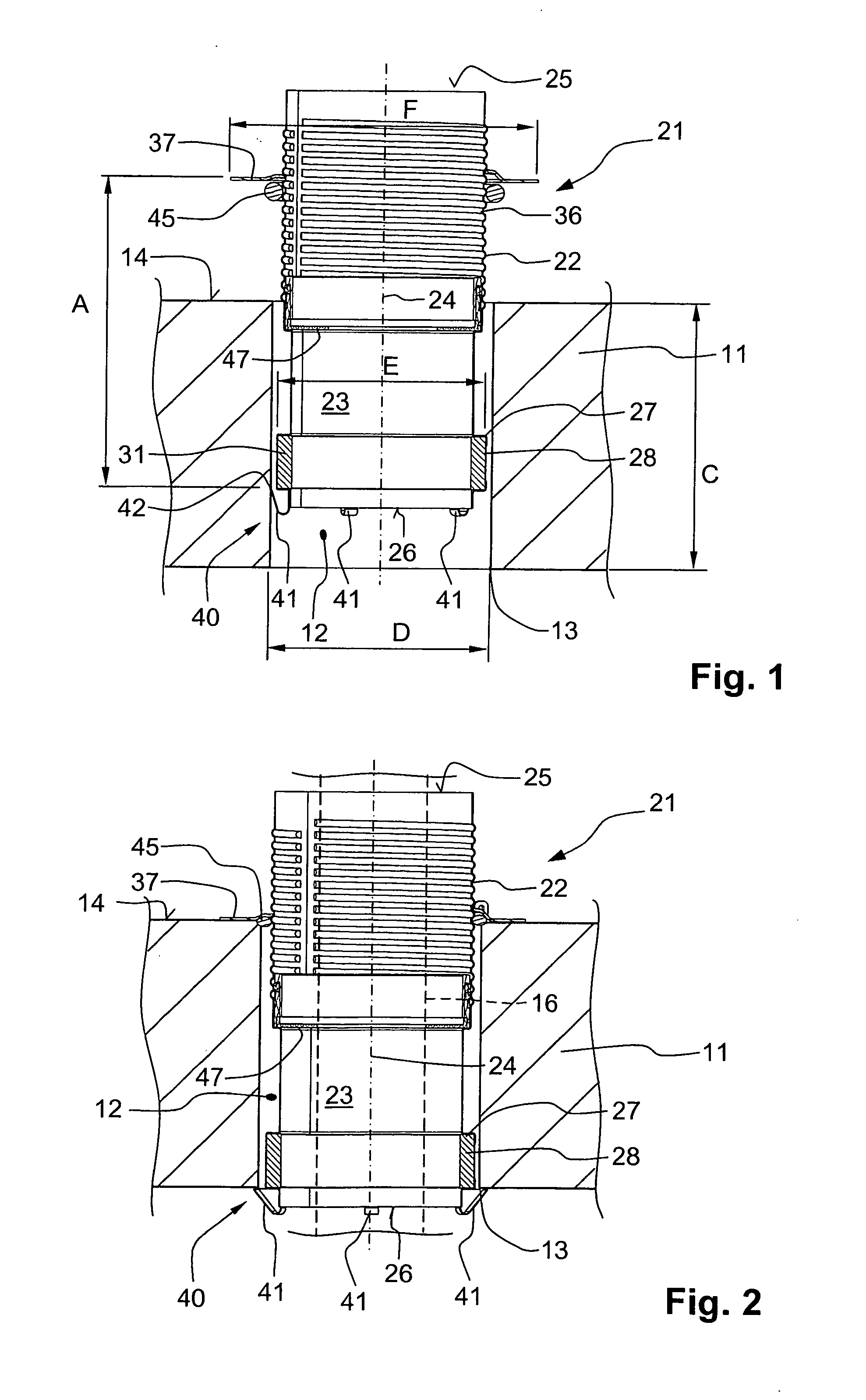
[0038]A fire protection device 21, which is shown in FIGS. 1-2, will subsequently be arranged in a preliminary formed opening 12 in a constructional component 11 and serves for passing as well as for fireproofing of a conduit 16 through the constructional component 11.

[0039]The fire protection device 21 has a cylindrical housing 22 extending along a longitudinal axis 24 and having a through-opening 23 for the conduit 16, a first end 25, and an opposite end 26. The housing 22 further has a receiving chamber 27 opening toward the through-opening 23 in which a fireproof insert 31 of intumescent material is provided.

[0040]The outer wall of the receiving chamber 27 is provided with openings 28 the function of which will be described further below. The maximal outer diameter E of the housing 22 is smaller than the inner diameter D of the opening 12 in the constructional component 11.

[0041]The housing 22 is provided with an outer thread 36 in the region of its first end 25. There is furthe...


PUM


Abstract

A fire protection device for mounting in a preliminary formed opening (12) in a constructional component (11) and for leading a conduit (16) therethrough includes a housing (22; 52) having a through-opening (23; 53) for the conduit (16), and a fireproof insert (31) provided in the through-opening (23), a first attachment device (35; 58) provided on the housing (22; 52) in a region of a first end (25) of the housing for securing the fire protection device (21; 51) in the constructional component (11), and a second attachment device (40; 60) provided in a region of the second end (26; 56) and having at least one attachment section displaceable between its insertion and attachment positions in which the fire protection device, respectively, is insertable in the opening in the constructional component and is fixed therein.

Description

BACKGROUND OF THE INVENTION[0001]1. Field of the Invention[0002]The present invention relates to a fire protection device for mounting in a preliminary formed opening in a constructional component and for leading a conduit through the constructional component, the fire protection device including a housing having a through-opening for the conduit, a first end, a second end located opposite the first end, and a fireproof insert provided in the through-opening, and further including a first attachment device provided on the housing in a region of the first end for securing the fire protection device in the constructional component.[0003]2. Description of the Prior Art[0004]In order to fireproof leadthroughs in a constructional component such as, e.g., a wall or a ceiling of a building, so that in case of fire, no fire or smoke would spread from one room to another room, U.S. Pat. No. 6,694,684 discloses a fire protection device cast directly in a constructional component.[0005]However...

Claims


Application Information

Patent Timeline
IPC IPC(8): A62C3/00
CPCA62C2/06H02G3/22H02G3/0412F16L5/04
Inventor MONDEN, THOMASMORDAU, ULF
Owner HILTI AG
Why Eureka
Try Eureka