Method and system for fast channel change

a channel change and channel technology, applied in the field of delay reduction, can solve the problem of a large delay before the decoding of the video stream can start, and achieve the effect of minimizing the total tim

Active Publication Date: 2011-03-24
ESPIAL GROUP
View PDF1 Cites 22 Cited by
  • Summary
  • Abstract
  • Description
  • Claims
  • Application Information

AI Technical Summary

Benefits of technology

The present invention provides systems and methods for quickly changing channels between different networks without causing delays. It involves creating slots within certain types of multicast data streams, which helps reduce the time it takes to switch between different networks. Additionally, it suggests adding these slots after they are inserted into an existing network's database. This allows users to easily adjust the times when they want to join multiple networks together. Overall, this technology improves efficiency and performance in communication networks.

Problems solved by technology

This patent describes various technical problem addressed in this patent text: how to compress videos efficiently without sacrificing quality during playback on different devices like televisions and computers. Current methods require either I-frames or P-or B-frames, making it difficult to decode certain types of data quickly enough.

Method used


Image

  • Method and system for fast channel change
  • Method and system for fast channel change
  • Method and system for fast channel change

Examples


Embodiment Construction

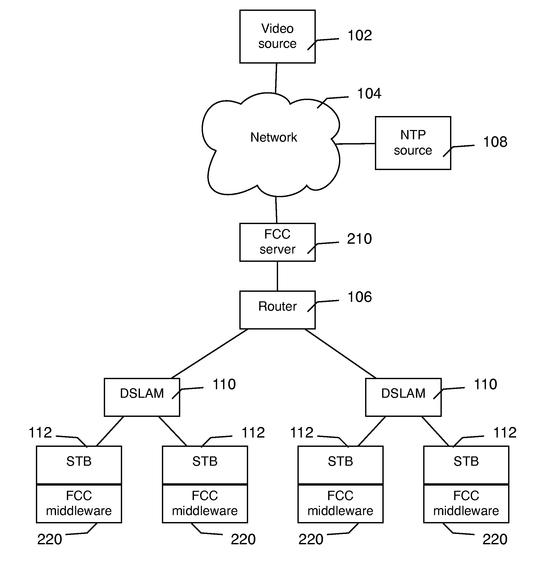
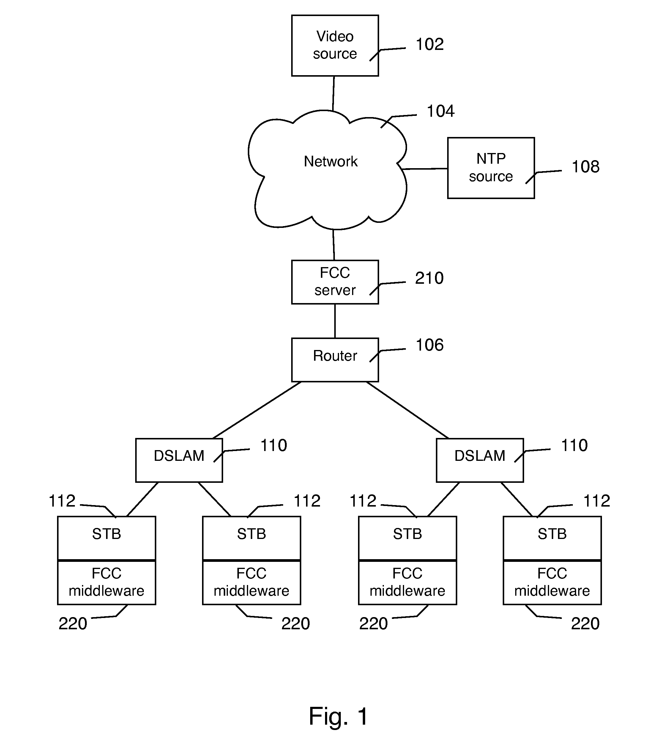
[0017]FIG. 1 is a schematic representation of an exemplary system 200 for fast channel change (FCC), comprising a FCC server 210 and a plurality of FCC middleware components 220, illustrated in a typical operating environment. The operating environment includes a video source 102, a network 104, a NTP source 108, a router 106, one or more digital subscriber line access multiplexers (DSLAM) 110 and a plurality of set-top boxes (STB) 112. The video source 102 can be a cable head-end or other similar source of a plurality of compressed, multicast video streams (i.e. channels). The video streams are transmitted over a network 104 to one or more systems 200. The network 104 can be, for example, any well-known broadband transmission infrastructure such as those typically deployed by telecommunications operating companies (a.k.a. telco's). The FCC server 210 can receive one or more of the multicast video streams (i.e. channels) from the video source 102. Video streams output by the FCC server


PUM


Abstract

A method and system for fast channel change (FCC) between multicast digital video feeds wherein each digital video feed is converted to a set of slotted multicasts, each having the same content but delayed in time relative to each other, metadata associated with the digital video feed and the slotted multicasts is published using an on-the-wire format to downstream client devices (e.g. set-top boxes), when a user selects the digital video feed (i.e. a new channel) the client device uses the metadata to select a slotted multicast that minimizes the total time to reach the next random access point (RAP) while allowing a maximum leave-join delay. Both a FCC server that generates the slotted multicasts and a FCC middleware on the client devices are connected to a common time reference, and the method and system provide for adjusting to clock drift on the FCC server relative to the common time reference.

Description


Claims


Application Information

Patent Timeline
Owner ESPIAL GROUP
Why Eureka
Try Eureka