Connector and connector combination for balanced transmission
a technology of balanced transmission and connectors, applied in the direction of coupling contact members, connection contact member materials, coupling device connections, etc., can solve the problems of unbalanced transmission, unbalanced transmission transmitting data, difficult to reduce pitch, etc., to reduce the number of parts, reduce pitch, and high-speed signal transmission
- Summary
- Abstract
- Description
- Claims
- Application Information
AI Technical Summary
Benefits of technology
Problems solved by technology
Method used
Image
Examples
first embodiment
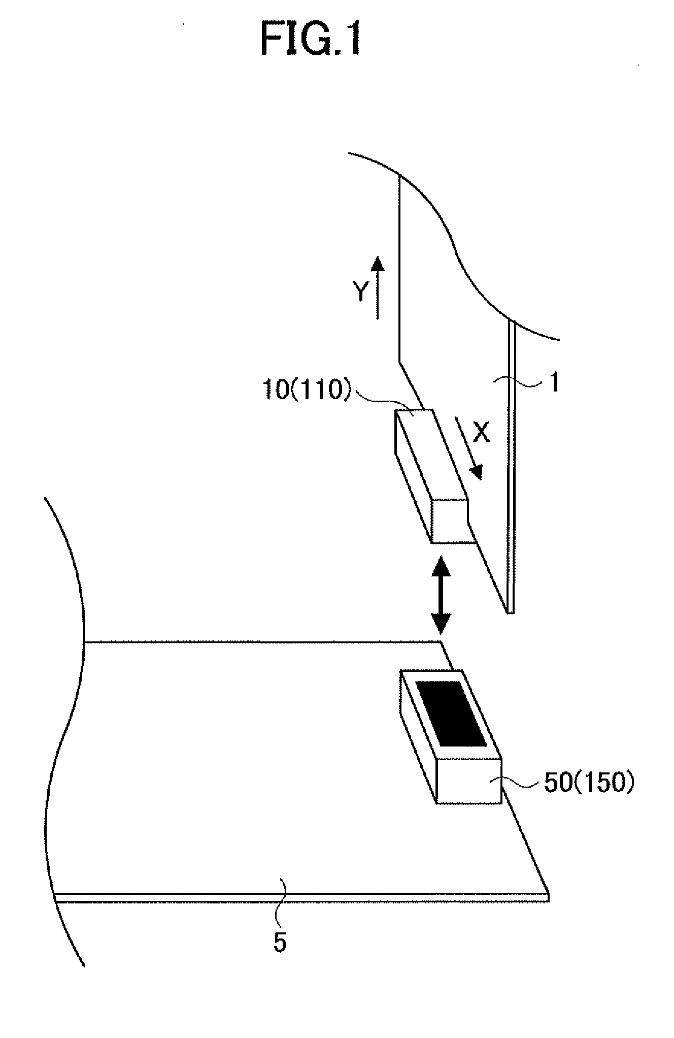
[0028]A description will be given of the connector in a first embodiment of the present invention.
[0029](Plug Connector)
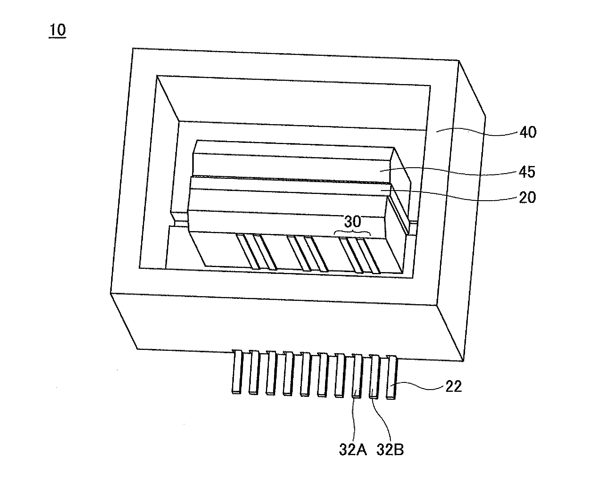
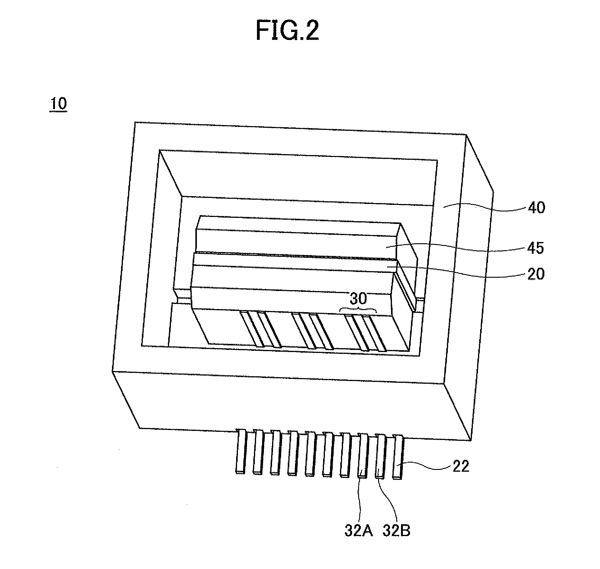
[0030]FIG. 2 is a perspective view illustrating an example of the plug connector in the first embodiment of the present invention. FIG. 3 is a perspective view illustrating conductor parts of the plug connector in the first embodiment, by omitting illustration of insulator parts.
[0031]As illustrated in FIGS. 2 and 3, the plug connector 10 includes a (first) ground contact 20 and a plurality of (first) signal contact pairs 30. The ground contact 20 and the plurality of signal contact pairs 30 are formed by a conductor material which may be selected from metals including metals suited for the balanced transmission.
[0032]As illustrated in FIG. 3, the ground contact 20 may be formed by a plate-shaped member extending in the direction X, that is, in the longitudinal direction of the plug connector 10. A plurality of lead parts 22 alternately extend towards mutually opposit
second embodiment
[0055]A description will be given of the connector in a second embodiment of the present invention.
[0056](Plug Connector)
[0057]FIG. 9 is a perspective view illustrating conductor parts of the plug connector in a second embodiment of the present invention. Signal contacts of a plug connector 110 in this embodiment may be the same as that of the first embodiment described above, and thus, illustration and description thereof will be omitted. A (first) ground contact 120 illustrated in FIG. 9 may be formed by a conductor material which may be selected from metals including metals suited for the balanced transmission.
[0058]The ground contact 120 is formed by a plate-shaped member extending in the longitudinal direction (X) of the plug connector 110, and a plurality of slits 124 are formed in the plate-shaped member, as illustrated in FIG. 9. Of course, the plate-shaped member may only include a single slit 124. A plurality of lead parts 122 alternately extend towards mutually opposite side
PUM
 Abstract
Description
Claims
Application Information
 - R&D Engineer
- R&D Manager
- IP Professional
- Industry Leading Data Capabilities
- Powerful AI technology
- Patent DNA Extraction
Browse by: Latest US Patents, China's latest patents, Technical Efficacy Thesaurus, Application Domain, Technology Topic.
© 2024 PatSnap. All rights reserved.Legal|Privacy policy|Modern Slavery Act Transparency Statement|Sitemap


