Printing system having printhead bypass

a printing system and printhead technology, applied in the field of fluid systems and apparatuses, can solve the problems of unwieldy individual pressure regulators integrated into each printhead, unfavorable multi-color printing, and inability to achieve the effect of reducing the number of printing heads, improving the efficiency of printing, and improving the reliability

Inactive Publication Date: 2011-11-17
ZAMTEC
View PDF17 Cites 11 Cited by
  • Summary
  • Abstract
  • Description
  • Claims
  • Application Information

AI Technical Summary

Benefits of technology

The technical effect in this patented method is how it can be used with different types of printers without requiring complicated equipment or modifications. This makes it easier than previous methods but still works well enough even at medium-large printings where multiple copies are needed on both sides simultaneously.

Problems solved by technology

The technical problem addressed in this patented text relating to improving image quality during ink jet printing processes while reducing costs associated with maintaining precise control over the movement and timing of the paper being printed. Current methods involve increasing the size of the print head used but they also lead to increased complexity and high maintenance requirements due to their mechanical nature. There needs an improved methodology for achieving better liquid dispersion efficiency at both small and medium sizes.

Method used


Image

  • Printing system having printhead bypass
  • Printing system having printhead bypass
  • Printing system having printhead bypass

Examples


Embodiment Construction

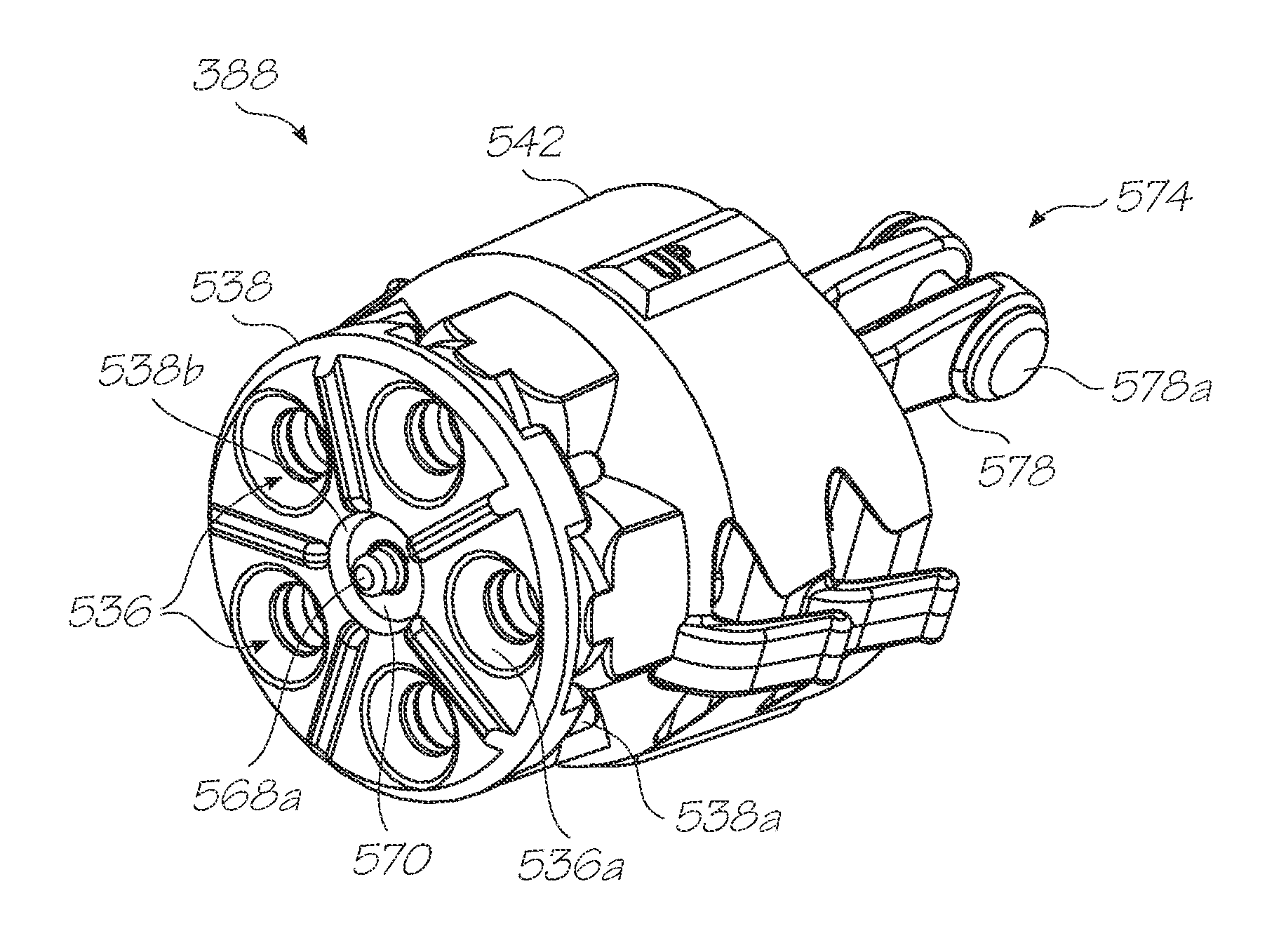
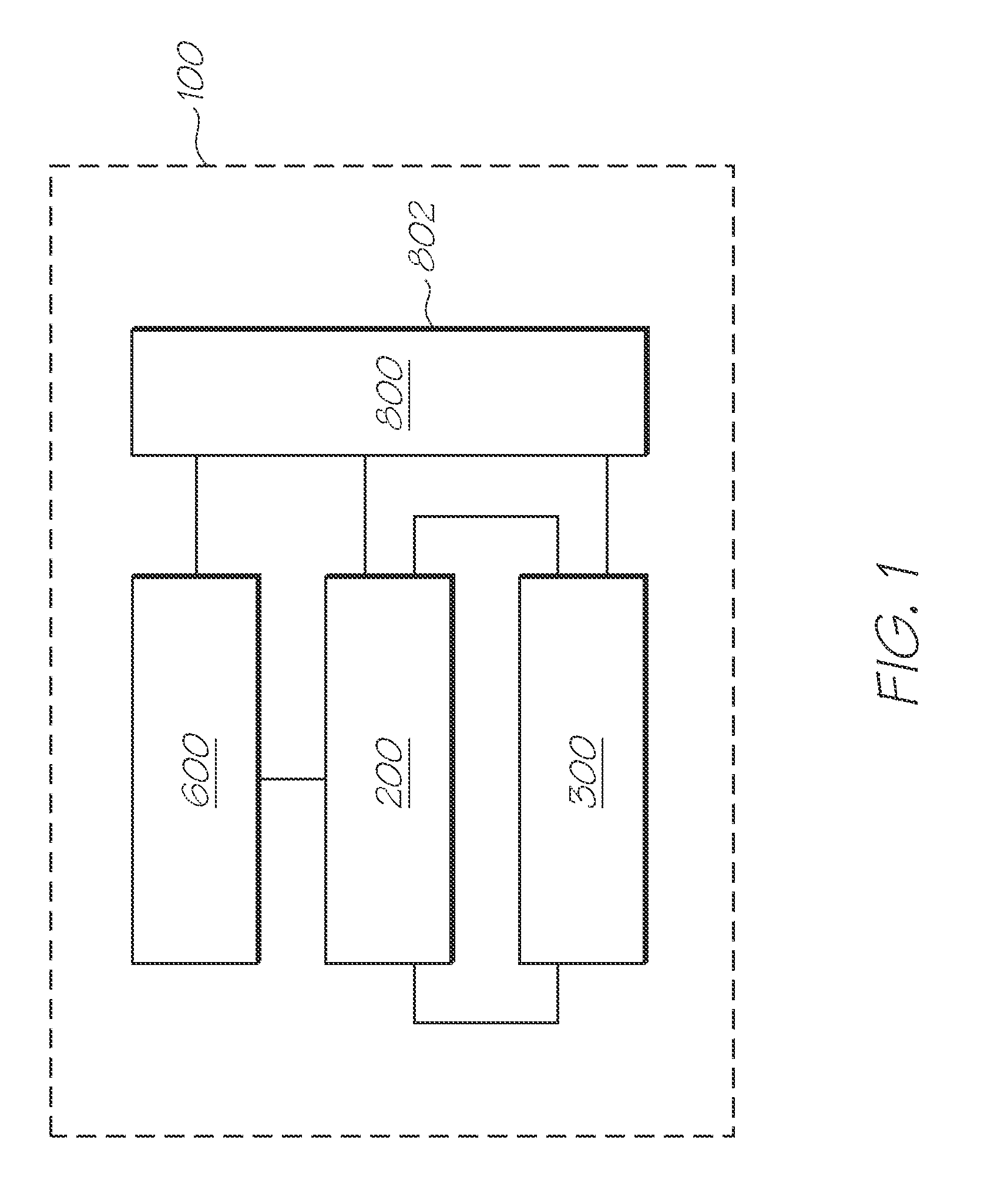
[0620]An exemplary block diagram of the main system components of a printer 100 is illustrated in FIG. 1. The printer 100 has a printhead 200, fluid distribution system 300, maintenance system 600 and electronics 800.

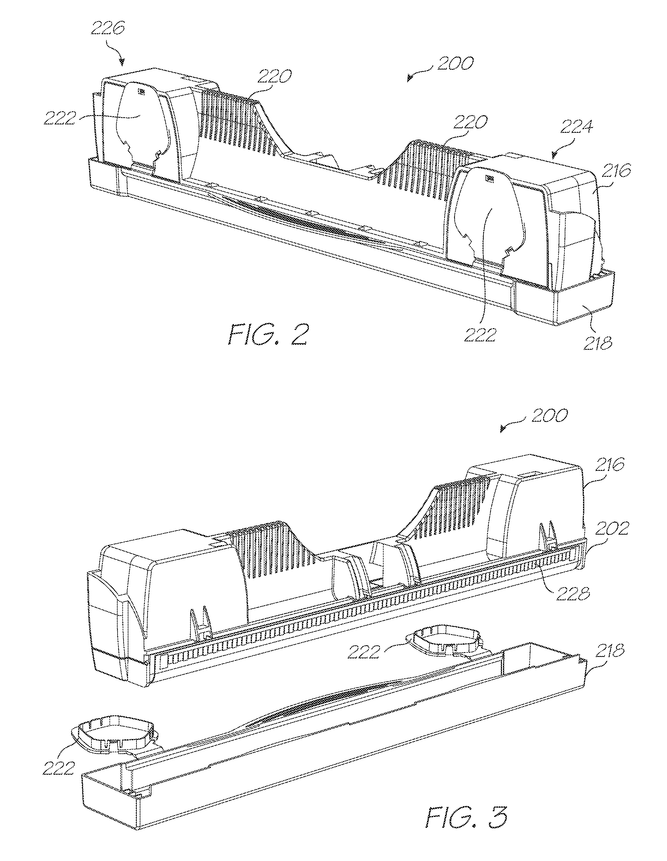
[0621]The printhead 200 has fluid ejection nozzles for ejecting printing fluid, such as ink, onto passing print media. The fluid distribution system 300 distributes ink and other fluids for ejection by the nozzles of the printhead 200. The maintenance system 600 maintains the nozzles of the printhead 200 so that reliable and accurate fluid ejection is provided.

[0622]The electronics 800 operatively interconnects the electrical components of the printer 100 to one another and to external components / systems. The electronics 800 has control electronics 802 for controlling operation of the connected components. An exemplary configuration of the control electronics 802 is described in US Patent Application Publication No. 20050157040 (Applicant's Docket No. RRC001US), the cont


PUM

PropertyMeasurementUnit
Volumeaaaaaaaaaa
Lengthaaaaaaaaaa
Lengthaaaaaaaaaa

Abstract

A printing system having a media width printhead having a first fluid port at one longitudinal end of the media width and a second fluid port at the other longitudinal end of the media width; a first fluid path connected to the first fluid port of the printhead, a second fluid path connected to the second fluid port of the printhead, a third fluid path interconnecting the first and second paths, wherein the first, second and third paths are configured so that fluid flows between the first and second paths via the printhead and via the third fluid path.

Description


Claims


Application Information

Patent Timeline
Owner ZAMTEC
Why Eureka
Try Eureka