Method and apparatus for determining sleep states

a technology of sleep state and automatic determination, applied in the field of methods and apparatus for automatically determining sleep state, can solve the problems of low iq in children, affecting the quality of sleep,

Active Publication Date: 2011-12-08
THE UNIV OF QUEENSLAND
View PDF7 Cites 44 Cited by
  • Summary
  • Abstract
  • Description
  • Claims
  • Application Information

AI Technical Summary

Benefits of technology

This patent describes a method called sleep analysis, which helps predict how well people are going through their sleeping cycle. It involves analyzing data collected during the course of one's sleep period to determine factors like sleepiness levels or breathing patterns. These factors help researchers better understand what causes them to be tired more quickly and at home.

Problems solved by technology

The technical problem addressed in this patent text is the difficulty in accurately identifying sleep-related parameters in real-world sleep studies without requiring experts trained in the field. Current methods require manual input and evaluation, leading to inconsistent findings and potential errors.

Method used


Image

  • Method and apparatus for determining sleep states
  • Method and apparatus for determining sleep states
  • Method and apparatus for determining sleep states

Examples


Embodiment Construction

2. Method

2.1 EEG Data Acquisition

[0106]The clinical data acquisition environment for this work is the Sleep Diagnostic Laboratory of The Prince Alexandra Hospital, Australia. The data was recorded using clinical Polysomnography (PSG) equipment (Siesta, Compumedics®, Sydney, Australia). Patient preparation, electrode placement and instrumental set-up were done by an experienced sleep technician according to AASM guidelines [9]. Table 3 describes the demographic details of the subjects studied.

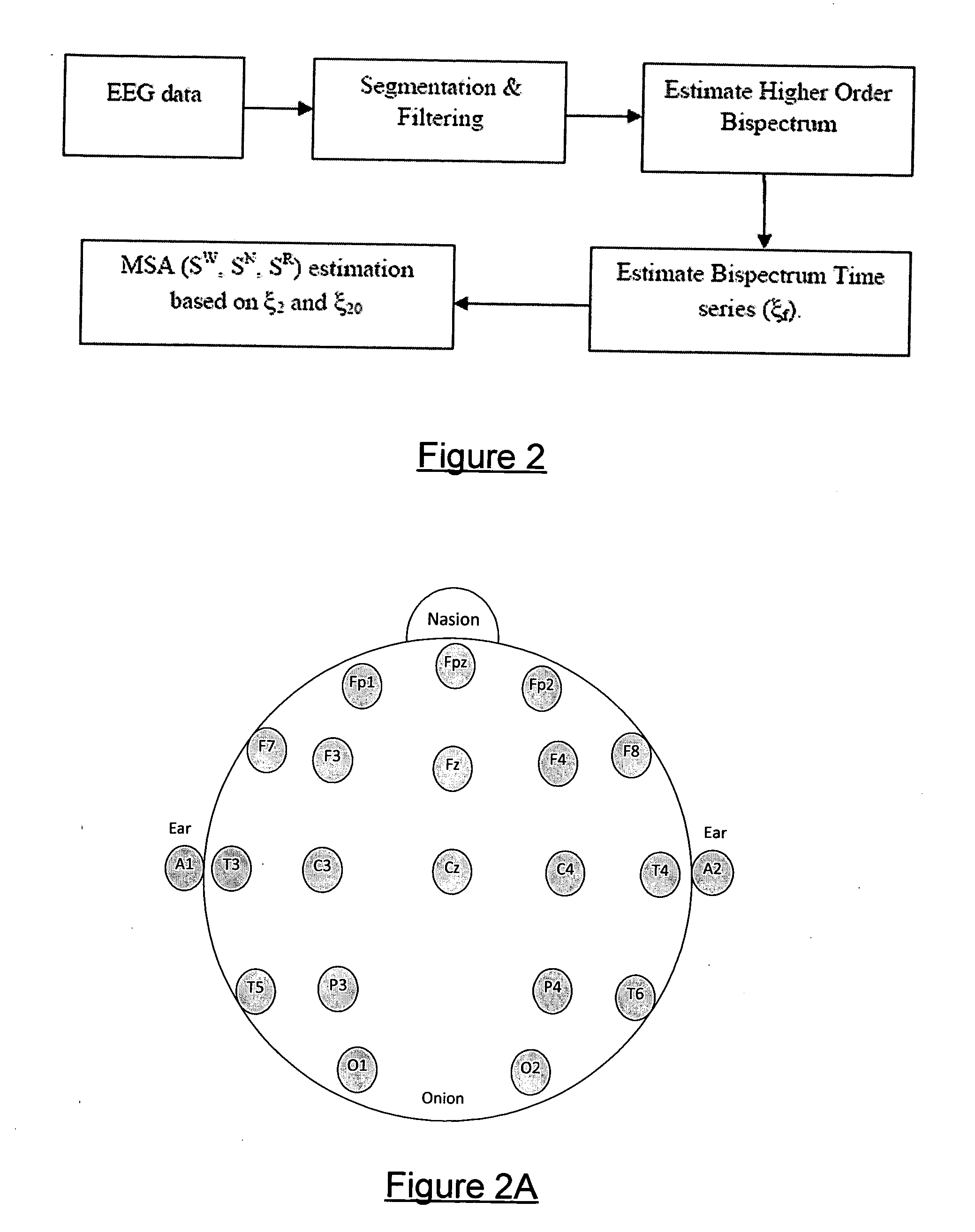
[0107]Database A: From each subject in this database, routine PSG data was collected. In a typical PSG test, signals such as ECG, EEG, EMG, EOG, nasal / oral airflow, respiratory effort, body positions, body movements and blood oxygen saturation are monitored. EEG data was recorded from both hemispheres using electrode positions C4, C3, A2, and A1, based on the standard international 10-20 system of electrode placement [10] illustrated in FIG. 2A. The subject population includes individuals with sy


PUM


Abstract

An apparatus is provided for detecting Macro Sleep Architecture states of a subject such as WAKE, NREM and REM sleep from a subject's EEG. The apparatus includes an EEG digital signal assembly of modules arranged to convert analogue EEG signals into digital EEG signals. A bispectrum assembly is responsive to the EEG digital signal assembly and converts the digital EEG signals into signals representing corresponding bispectrum values. A bispectrum time series assembly, in electrical communication with an output side of the bispectrum assembly, generates at least one bispectrum time series for a predetermined frequency. A macro-sleep architecture (MSA) assembly is responsive to the bispectrum time series assembly and is arranged to produce classification signals indicating classification of segments of the EEG signals into macro-sleep states of the subject.

Description


Claims


Application Information

Patent Timeline
Owner THE UNIV OF QUEENSLAND
Why Eureka
Try Eureka