System for improving engine crankcase ventilation via a conduit

Inactive Publication Date: 2012-03-01
FORD GLOBAL TECH LLC
View PDF7 Cites 6 Cited by
  • Summary
  • Abstract
  • Description
  • Claims
  • Application Information

AI Technical Summary

Benefits of technology

[0002]An engine provides torque by combusting an air-fuel mixture in an engine cylinder. The combustion increases pressure and temperature within the cylinder to cause a piston within the cylinder to move. The moving piston applies a force to the engine crankshaft and causes it to rotate, thereby providing engine output torque. However, some portion of the cylinder gases may pass by the piston and enter the engine crankcase. The gases that enter the engine crankcase can be evacuated and reintroduced to the engine intake system so that engine hydrocarbon emissions may be reduced. In some engine systems, the crankcase gases flow from the

Problems solved by technology

However, some portion of the cylinder gases may pass by the piston and enter the engine crankcase.
Although evacuating the engine crankcase of gases can reduce engine emissions, it also poses other issues.
In particular, the possibility of drawing oil from the engine crankcase and cylinder heads to the PCV path increases when the engine i

Method used


Image

  • System for improving engine crankcase ventilation via a conduit
  • System for improving engine crankcase ventilation via a conduit
  • System for improving engine crankcase ventilation via a conduit

Examples


Embodiment Construction

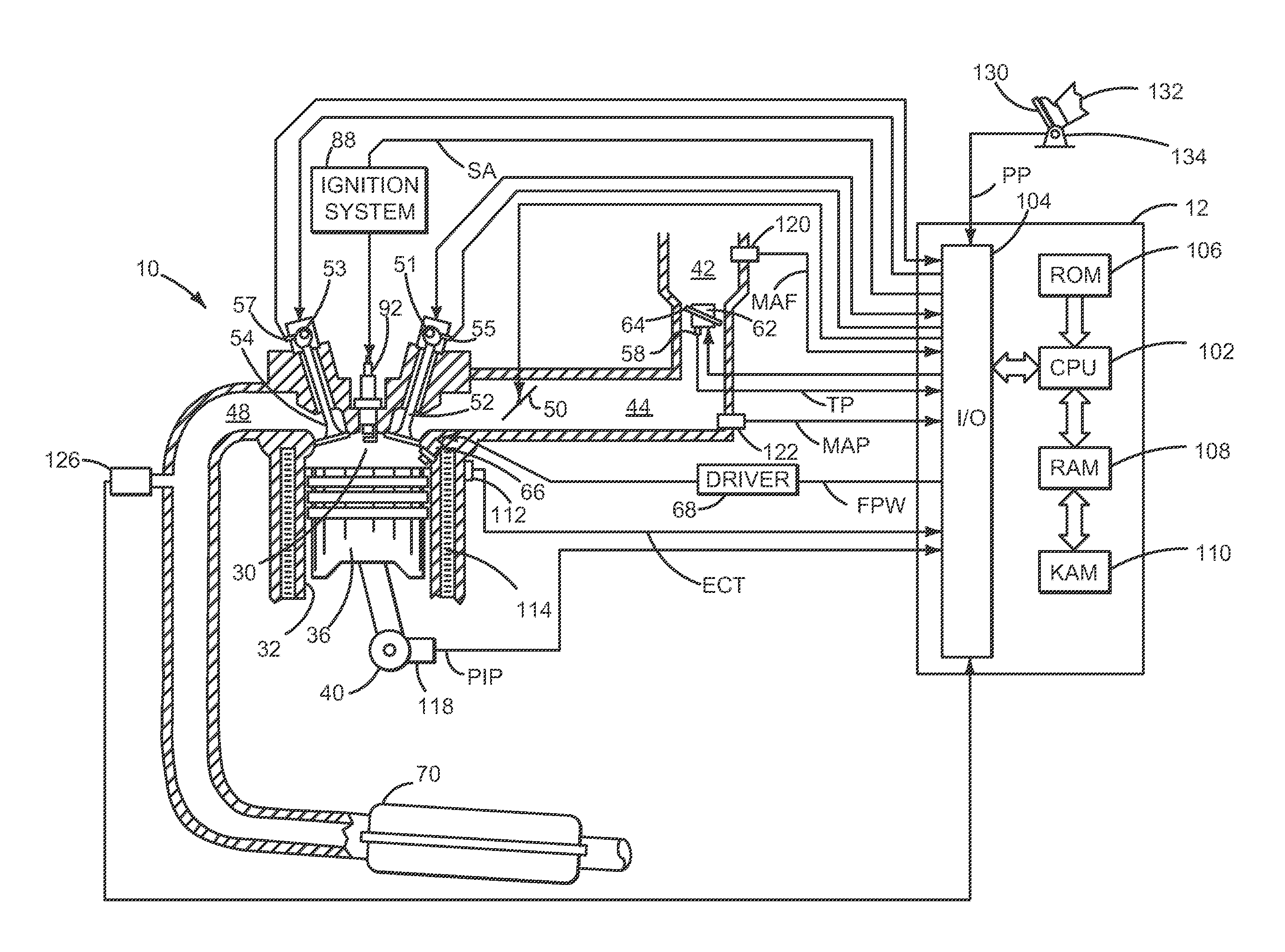
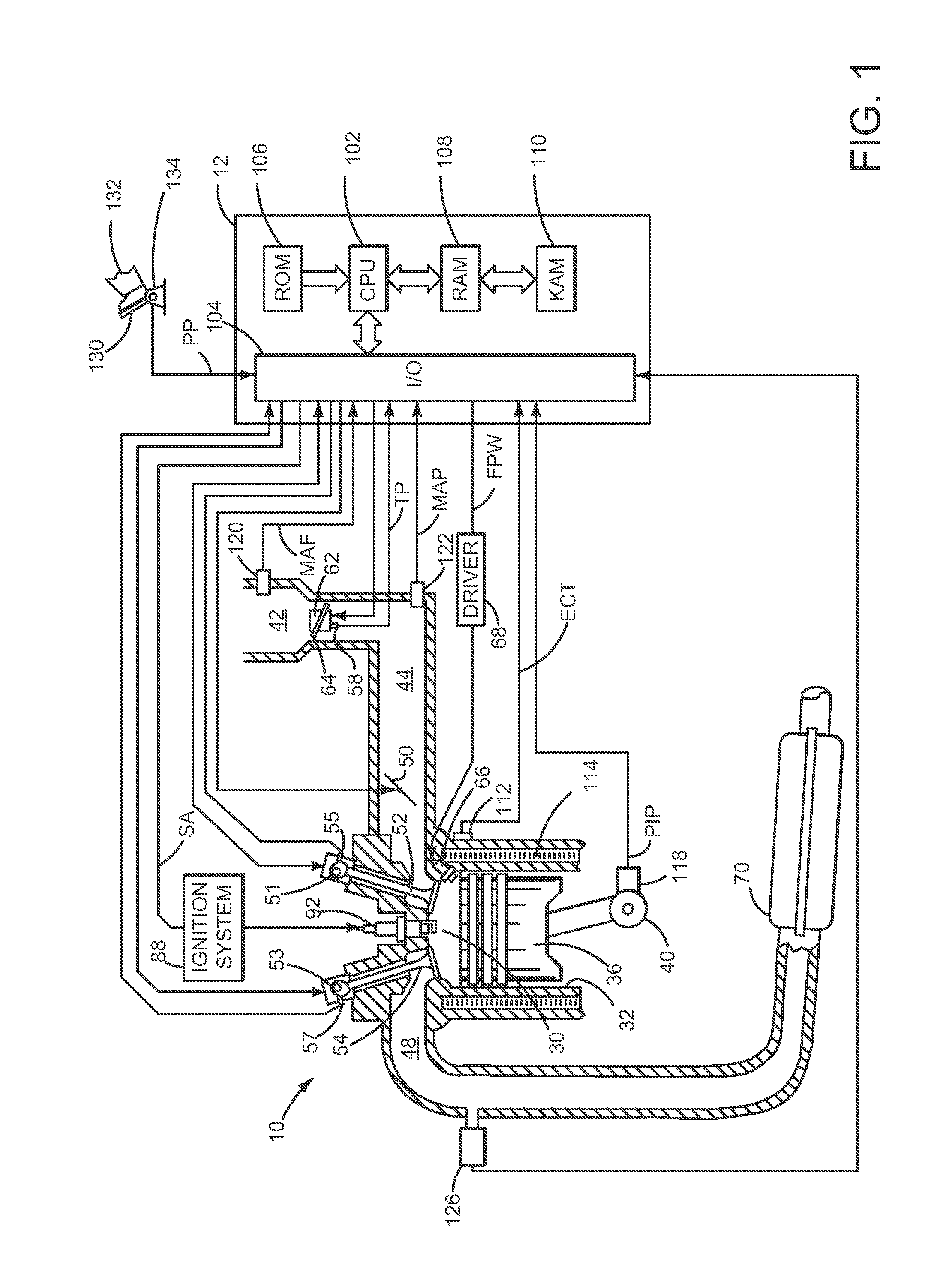
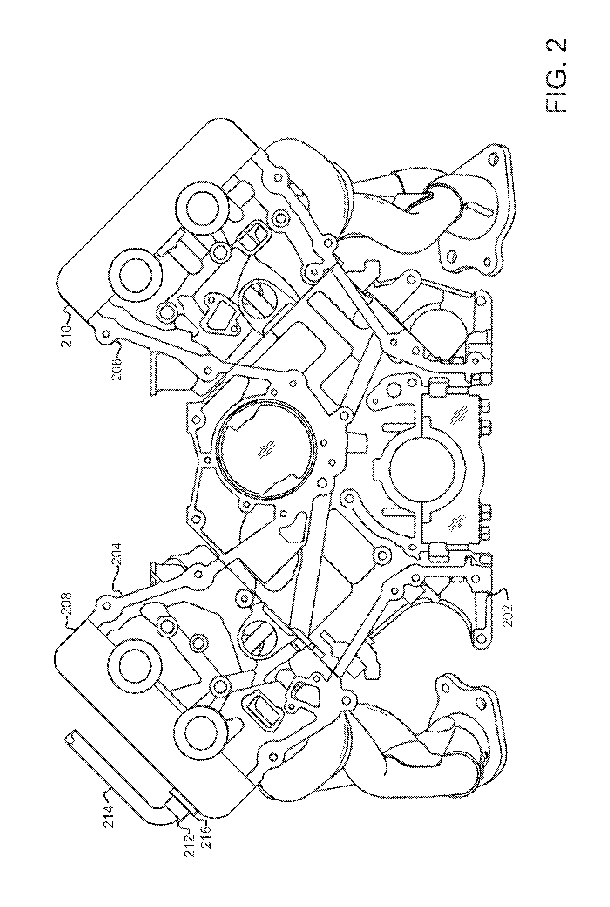
[0020]The present description is related to PCV flow of an internal combustion engine. In one embodiment, an eight cylinder engine as shown in FIG. 2 and having a lateral force PCV valve as shown in FIGS. 3-6B improves PCV flow by limiting oil intrusion into the PCV path. FIG. 7 shows a method for controlling PCV flow during periods of higher lateral or centripetal forces.

[0021]Referring to FIG. 1, internal combustion engine 10, comprising a plurality of cylinders, one cylinder of which is shown in FIG. 1, is controlled by electronic engine controller 12. Engine 10 includes combustion chamber 30 and cylinder walls 32 with piston 36 positioned therein and connected to crankshaft 40. Combustion chamber 30 is shown communicating with intake manifold 44 and exhaust manifold 48 via respective intake valve 52 and exhaust valve 54. Each intake and exhaust valve may be operated by an intake cam 51 and an exhaust cam 53. Alternatively, one or more of the intake and exhaust valves may be operate


PUM


Abstract

A system for improving PCV flow of an engine is presented. The system can reduce engine oil consumption when an engine is exposed to lateral or centripetal force. In one example, the system includes a mechanically operated valve that acts to limit PCV flow in a conduit external to an engine.

Description


Claims


Application Information

Patent Timeline
Owner FORD GLOBAL TECH LLC
Why Eureka
Try Eureka