High-flow vacuum generator

A vacuum generator and large flow technology, which is applied in the direction of machines/engines, non-volume pumps, mechanical equipment, etc., can solve the problem of inconvenient removal of small and small products, and achieve improved gas source utilization, fast speed, and large flow Effect

Inactive Publication Date: 2015-04-15
STAR SEIKI XIANGYANG
View PDF5 Cites 3 Cited by
  • Summary
  • Abstract
  • Description
  • Claims
  • Application Information

AI Technical Summary

Benefits of technology

This new technology allows for better use of an evacuated chamber called a tube instead of just one space inside which there's only one way to get rid of excessive heat or humidity during manufacturing processes. By making sure this gap fits properly within certain dimensions, these improvements improve the performance and durability of the equipment while also reducing its size without compromising their functionality.

Problems solved by technology

The technical problem addressed in this patented text relates to finding an efficient way to remove injected or extruded thermoplastic resin (TPE) parts during manufacturing processes such as injection molds without causing any unwanted effects like vibrations caused when removing them.

Method used


Image

  • High-flow vacuum generator
  • High-flow vacuum generator
  • High-flow vacuum generator

Examples


Embodiment Construction

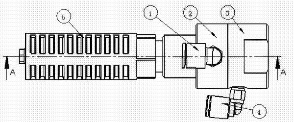
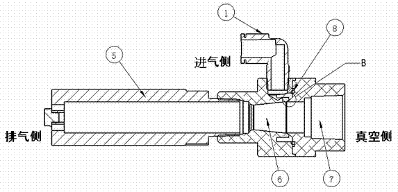
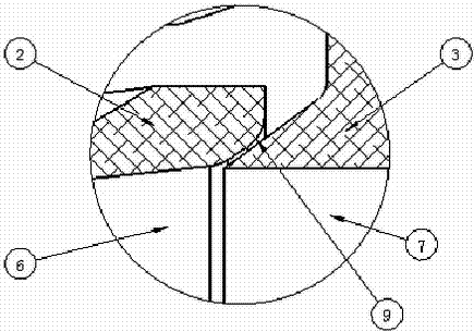
[0016] Such as figure 1 , figure 2 , image 3 , Figure 4 , Figure 5 As shown, the diffusion side bracket 2 and the vacuum side bracket 3 are made of super duralumin material, and are anodized; the two ends of the diffusion side bracket 2 are respectively connected with the vacuum side bracket 3 and the muffler 5; There is a diffusion chamber 6, and the vacuum side bracket 3 has an adsorption chamber 7, one end of the diffusion chamber 6 communicates with the adsorption chamber 7, and the other end of the diffusion chamber 6 is connected to the muffler 5; The side support 3 is equipped with a trachea joint 2 4, the trachea joint 1 communicates with the diffusion chamber 6, and the trachea joint 2 4 communicates with the adsorption chamber 7; the gap formed between the diffusion side support 2 and the vacuum side support 3 is a high-speed The nozzle 9 of the jet; the sealing ring 8 is arranged between the diffuser side bracket 2 and the vacuum side bracket 3 .

[0017] Whe


PUM


Abstract

Disclosed is a high-flow vacuum generator, which relates to automatic industrial equipment for injection moulding. One end of a diffusion side stand is connected with a vacuum side stand while the other end is connected with a muffler. A diffusion chamber is arranged in the diffusion side stand, and an adsorption chamber is disposed in the vacuum side stand, wherein one end of the diffusion chamber communicates with the adsorption chamber and the other end of the diffusion chamber is connected to the muffler. The diffusion side stand is equipped with a first air tube joint and the vacuum side stand is equipped with a second air tube joint, wherein the air tube joint one communicates with the diffusion chamber and the second air tube joint communicates with the absorption chamber. A clearance formed between the diffusion side stand and the vacuum side stand is used as a nozzle for generating a high-speed jet. According to the invention, the high-flow vacuum generator has a small vacuum capacity, quick response, light weight, low noise, small vacuum, and a high flow. The high-flow vacuum generator is designed of a tubular shape, is flexibly connected to a clamp plate, is higher in taking-out accuracy and high in taking-out speed, has a vacuum breaking function, and is able to convert vacuuming into blowing. When a product is taken out by a clamp and the product needs to be released, the product can be blew out quickly.

Description


Claims


Application Information

Patent Timeline
Owner STAR SEIKI XIANGYANG
Why Eureka
Try Eureka