Chemical mechanical stirrer based on paddle wing barbs for organic silica gel

A technology of organic silica gel and chemical machinery, which is applied in the field of chemical mixing, which can solve the problems of sudden stop and paralysis, wear and tear of the mixer, and reduce the efficiency, quality and time period of the processing process.

Inactive Publication Date: 2020-06-26
吴金元
View PDF0 Cites 3 Cited by
  • Summary
  • Abstract
  • Description
  • Claims
  • Application Information

AI Technical Summary

Benefits of technology

This technology has several benefits over existing methods for treating blood vessels or other body tissues by applying heat therapy.

Problems solved by technology

This patented technical problem addressed by the present inventors relates to optimizing the performance of an existing chemical machine called Chemical Mechanical Mixers (CMP), specifically when treating lenses with different types of organics like gel or silicon gel. These machines use special tools to break up large pieces into smaller particles before they enter the chamber where other processes take place. However, these techniques have drawbacks including irregular particle sizes caused by gravity during rotation, excessive pressure on certain parts leading to damage from collisions between them, and potential issues related to lubricants being left inside the system after it has been processed through the CMP tool.

Method used


Image

  • Chemical mechanical stirrer based on paddle wing barbs for organic silica gel
  • Chemical mechanical stirrer based on paddle wing barbs for organic silica gel
  • Chemical mechanical stirrer based on paddle wing barbs for organic silica gel

Examples


Embodiment 1

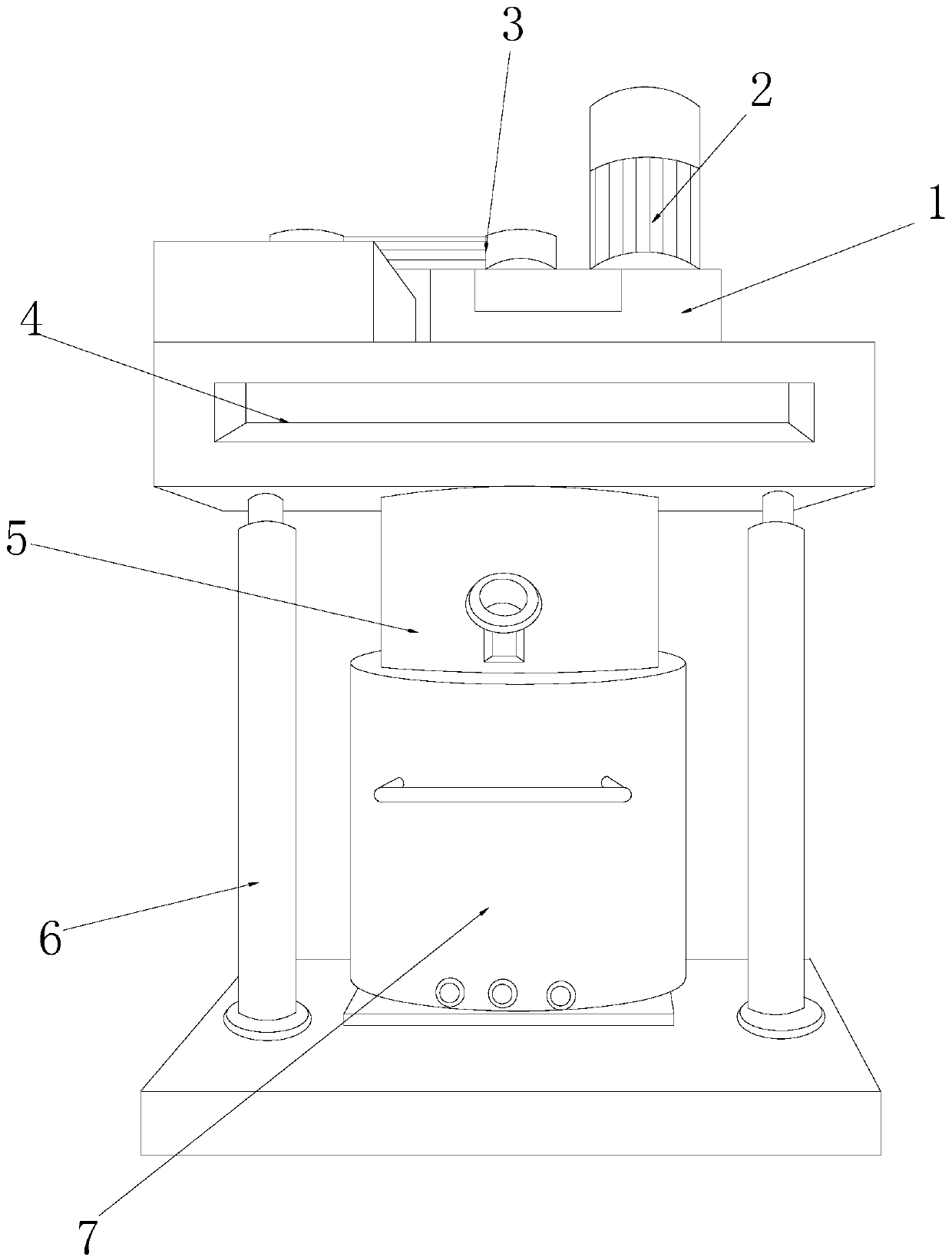
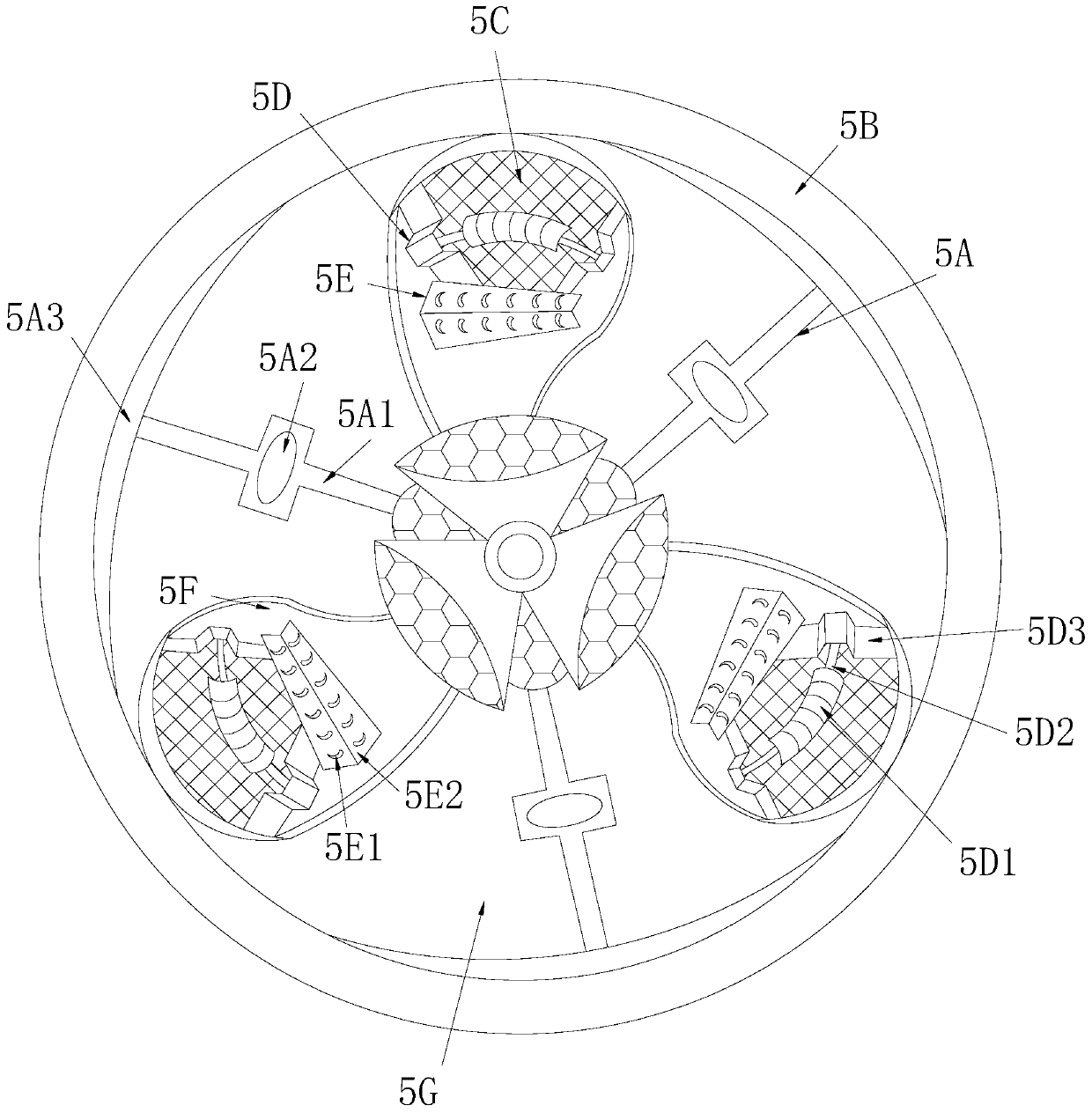
[0032] see Figure 1-Figure 6, the present invention provides a chemical machinery mixer based on paddle barbs for organic silica gel, its structure includes: gear box 1, shaft motor 2, transmission wheel belt 3, cover counterweight 4, propeller stirring tank tank 5. The hydraulic cylinder rod 6, the loading tank groove 7, the propeller stirring tank tank 5 is nested on the top of the loading tank tank 7 and communicates with each other, the shaft motor 2 is connected to the transmission wheel belt through the gear box 1 3 Mechanically connected, the gearbox 1 is installed on the top of the cover counterweight 4 and is on the same level, the cover counterweight 4 is nested on the top of the propeller stirring tank tank 5 and the axes are in common line, the cover counterweight 4 is mechanically connected with the hydraulic cylinder rod 6 and is perpendicular to each other. Stirring tank tank 5 is equipped with machete strut frame 5A, tank wall frame ring 5B, blade lining net 5C,

Embodiment 2

[0039] see Figure 1-Figure 6 , the present invention provides a kind of chemical machinery mixer based on the blade barb that organic silica gel is used, other respects are identical with embodiment 1, and difference is:

[0040] see figure 2 , the scimitar brace frame 5A is composed of rib buckle rod 5A1, ellipsoid rotor 5A2, and willow leaf machete 5A3. The willow leaf scimitar 5A3 and the rib buckle 5A1 are nested into one body, and the willow leaf scimitar 5A3 is rotated through the rib buckle 5A1 to form the circular cutting and granulation effect of the silicone thread, ensuring the effect of silicone reshaping and uniform granulation .

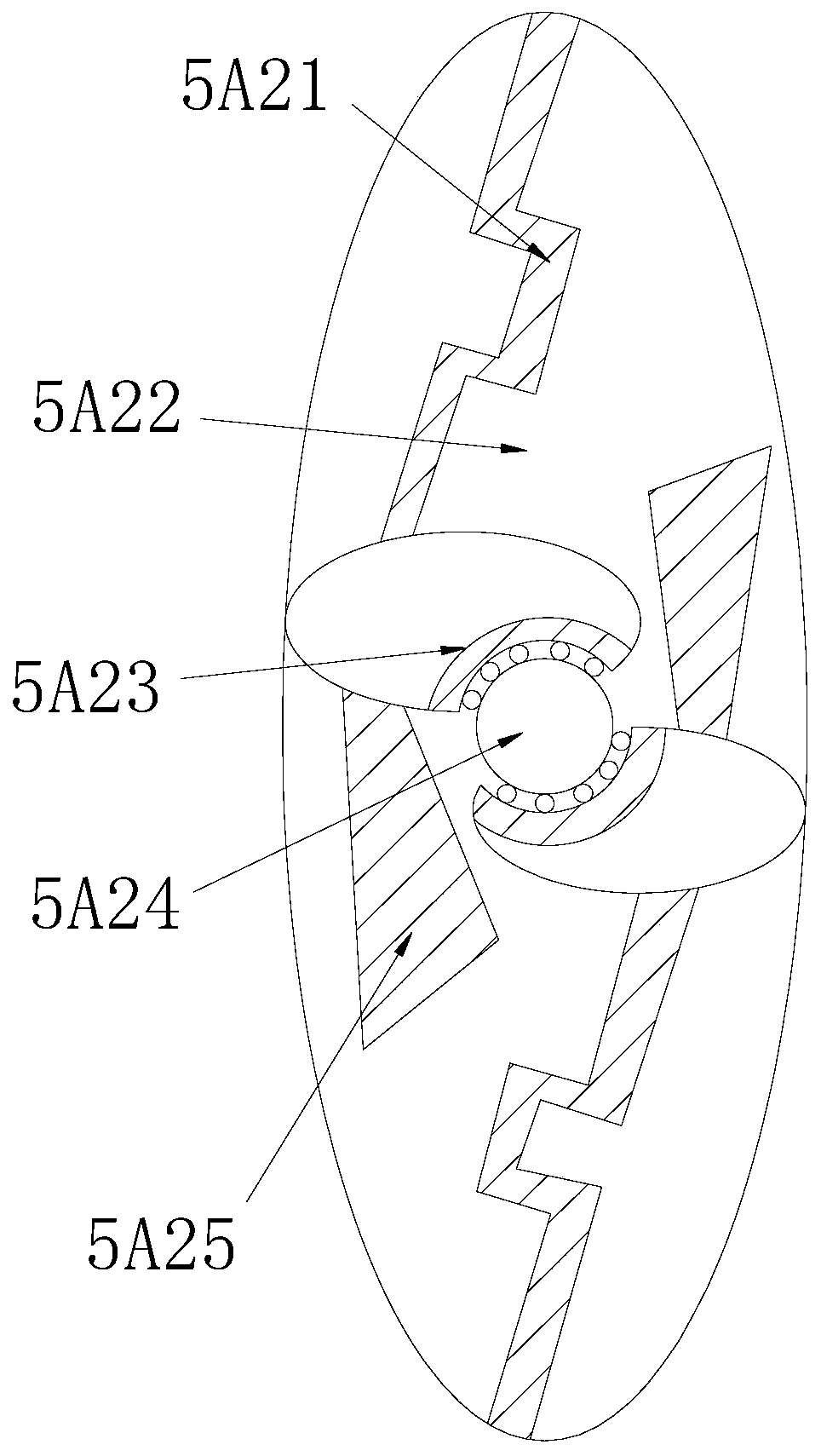
[0041] see image 3 The ellipsoidal rotor 5A2 is composed of a bow-shaped bead 5A21, an ellipsoidal shell groove 5A22, a ball petal 5A23, a rotor ball 5A24, and a fin plate 5A25. The two bead 5A21 are respectively inserted into On the upper and lower sides of the elliptical shell groove 5A22, the ball petals 5A23 and the rotor balls


PUM


Abstract

The invention discloses a chemical industry mechanical stirrer based on paddle wing barbs for organic silica gel. The chemical industry mechanical stirrer structurally comprises a gear box, a shaft driving motor, a conveying wheel belt, a cover balancing weight, a propeller stirring tank groove, a hydraulic cylinder rod and a material loading cylinder groove. According to the invention, the propeller stirring tank groove is matched with the material loading cylinder groove, so that the hook end block and the barb corn bending plate are matched to work to form linear rotary wire drawing; by matching with the twisting and hinging operation of the propeller, the granular sensation and the forming quality of the whole treated organic silica gel are high, the whole small fragments are uniform,the effect of rotary wire drawing is achieved, centripetal force operation is diffused, and the rotary floating action effect of the wire edge is formed; and the annular cutting effect is achieved through the bent knife supporting rod frame on the edge, so that the sealed rotary work of the isolation cover at the cap end of the axis rod is also guaranteed, the work rotary stirring efficiency is continuously guaranteed, the smooth annular track machining effect of chemical industry machinery is driven, and the high-performance machining effect of bottom loss is achieved along the inner tank barrel structure.

Description


Claims


Application Information

Patent Timeline
Owner 吴金元
Why Eureka
Try Eureka