Sewing machine and method of controlling operation of the same

Active Publication Date: 2012-06-14
SUNSTAR KK
View PDF12 Cites 1 Cited by
  • Summary
  • Abstract
  • Description
  • Claims
  • Application Information

AI Technical Summary

Benefits of technology

[0014]Accordingly, the present invention has been made keeping in mind the above problems occurring in the prior art, and an object of the present invention is to provide a sewing machine which can realize a perfect stitch

Problems solved by technology

Generally, objects, such as airbags, bags, shoes, etc., are made of comparatively thick materials and have many sewing lines, such as circular, curved, slanted lines, etc., which are difficult to sew.
Such hitch stitches make the entire stitch shape uneven, thus deteriorating the quality of the product.
Therefore, when t

Method used


Image

  • Sewing machine and method of controlling operation of the same
  • Sewing machine and method of controlling operation of the same
  • Sewing machine and method of controlling operation of the same

Examples


first embodiment

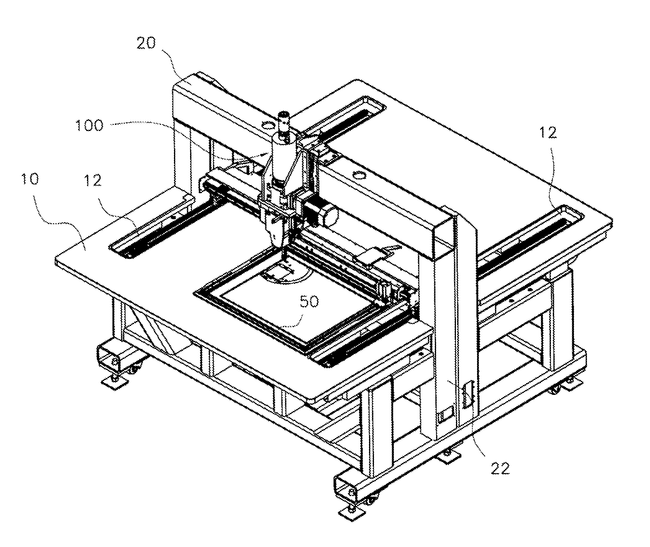
[0064]FIG. 3 is a perspective view of a head unit fixed sewing machine according to the present invention. FIG. 4 is a perspective view illustrating a head unit according to the present invention. FIG. 5 is a perspective view illustrating a bed unit according to the present invention.

[0065]In the head unit fixed sewing machine according to the present invention, the head unit 100 is disposed above a table 10. The head unit 100 sews an object which is supported by a sewing frame 50.

[0066]The table 10 is a rectangular plate onto which the object to be sewn is placed. Guide slots 12, which extend forwards and rearwards, are respectively formed in opposite sides of the table 10. The guide slots 12 are elongated holes, through which movement of a Y-axis transport means provided under the table 10 is transmitted to the sewing frame 50 provided on the table 10.

[0067]Support posts 22 which are placed upright are provided on the opposite sides of the table 10. An upper beam 20 is horizontally c

third embodiment

[0125]Meanwhile, as shown in FIG. 12, in the present invention, a plurality of groups of head units 100a and 100b which can be independently operated are provided on the upper beam 20. Furthermore, a plurality of groups of bed units which correspond to the respective groups of head units 100a and 100b are separately arranged. A plurality of sewing frames 50a and 50b are provided on the table 10 so that the groups of head units 100a and 100b can independently conduct the sewing operation on individual areas.

[0126]In detail, a plurality of groups of sewing, heads are separately provided on the upper beam 20 so as to be rotatable. Each of the sewing frames 50a and 50b which are provided on the table 10 and allow objects to be placed thereon can move in X-Y axis directions by an X-Y transport structure. Here, the number of X-Y transport structures is the same as that of the groups of sewing frames.

[0127]The method of placing the objects on the sewing frames 50 is as follows. Subsidiary sew


PUM


Abstract

A head unit fixed sewing machine is provided, which includes a table, support posts, an upper beam, a head unit and a bed unit. An object is placed on the table. The support posts are provided on opposite sides of the table. The upper beam connects the support posts to each other and is coupled to upper ends of the support posts. The head unit is fastened to the upper beam and has a head-unit-rotating means for rotating a sewing head within a predetermined range. The bed unit is provided below the head unit and has a bed-unit-rotating means for rotating a sewing bed within a predetermined range. Because the head unit and the bed unit can be rotated while sewing, the orientation of a sewn thread can be maintained constant. Hence, a perfect stitch can be realized over the entirety of the object.

Description


Claims


Application Information

Patent Timeline
Owner SUNSTAR KK
Why Eureka
Try Eureka