Method of piloting a multiple rotor rotary-wing drone to follow a curvilinear turn

Inactive Publication Date: 2012-09-13
PARROT
View PDF15 Cites 73 Cited by
  • Summary
  • Abstract
  • Description
  • Claims
  • Application Information

AI Technical Summary

Benefits of technology

[0043]Very advantageously, the setpoint values generated in step c) control the horizontal linear speed and the inclination of the drone in such a manner as to

Problems solved by technology

These two types of movement (in XY translation and in pivoting) may be performed simultaneously, but doing so requires a certain amount of skill.
This first method of operation (with controls that are dissociated) does not enable the drone to be piloted quickly.
However under circumstances the front camera in the drone no longer points in the forward direction of the drone, and the visual feedback on the screen of the appliance cannot be use

Method used


Image

  • Method of piloting a multiple rotor rotary-wing drone to follow a curvilinear turn
  • Method of piloting a multiple rotor rotary-wing drone to follow a curvilinear turn
  • Method of piloting a multiple rotor rotary-wing drone to follow a curvilinear turn

Examples


Embodiment Construction

[0060]There follows a description of an implementation of the invention.

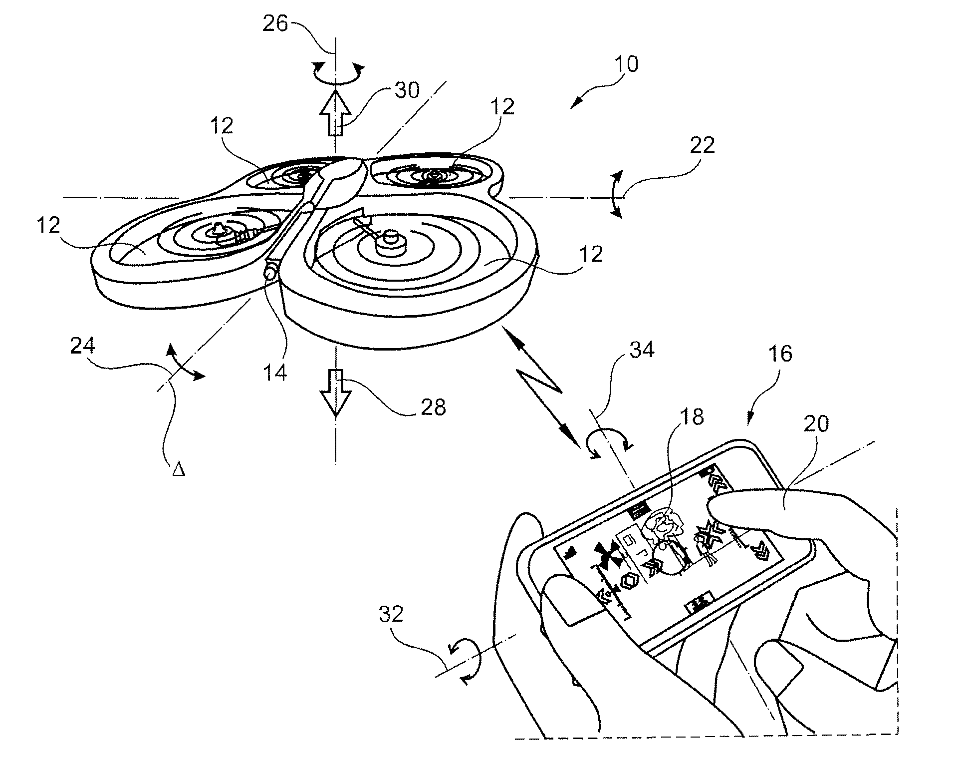
[0061]In FIG. 1, reference 10 is a general reference for a drone, which drone may for example be a quadricopter such as the model AR Drone from Parrot SA, Paris, France, as described in the above-mentioned WO 2010 / 061099 A2 and also in WO 2009 / 109711 A2 (which describes an example of an automatic stabilizer system operating on the basis of information supplied by an altimeter and a forward-looking camera) and FR 2 915 565 A1 (which describes in particular a gyro and accelerometer control system used by the drone).

[0062]The drone 10 has four coplanar rotors 12 driven by motors that are controlled independently by an integrated navigation and attitude control system. It is provided with a forward-looking, first camera 14 for obtaining an image of the scene towards which the drone is heading, e.g. a wide-angle CMOS sensor camera of VGA resolution (640×480 pixels) with a video stream refresh frequency of 15 frames


PUM


Abstract

The respective motors of the drone (10) can be controlled to rotate at different speeds in order to pilot the drone both in attitude and speed. A remote control appliance produces a command to turn along a curvilinear path, this command comprising a left or right turning direction parameter and a parameter that defines the radius of curvature of the turn. The drone receives said command and acquires instantaneous measurements of linear velocity components, of angles of inclination, and of angular speeds of the drone. On the basis of the received command and the acquired measurements, setpoint values are generated for a control loop for controlling motors of the drone, these setpoint values controlling horizontal linear speed and inclination of the drone relative to a frame of reference associated with the ground so as to cause the drone to follow curvilinear path (C) at predetermined tangential speed (u).

Description


Claims


Application Information

Patent Timeline
Owner PARROT
Why Eureka
Try Eureka