Operating mechanism for a bicycle multiple gear hub

Active Publication Date: 2012-11-01
SRAM
View PDF0 Cites 8 Cited by
  • Summary
  • Abstract
  • Description
  • Claims
  • Application Information

AI Technical Summary

Benefits of technology

[0010]An aspect of the invention is to create a simple device for introducing the gear shift or switch movement into the hub gears,

Problems solved by technology

In the prior art there are also articulating mechanisms which are mounted on the end of the hub axle in the form of so-called “axle switching devices.” They are prone to defects because they protrude over the other components of the bicycle in the direction of the hub axle, and they are considered to be troublesome.
Longitudinal bores and slots in axles are expensive to manufacture and lead to higher costs.
Since no quick release can be used with a hub axle with a longitudinal bore, the assembly and disassembly of the gea

Method used


Image

  • Operating mechanism for a bicycle multiple gear hub
  • Operating mechanism for a bicycle multiple gear hub
  • Operating mechanism for a bicycle multiple gear hub

Examples


Embodiment Construction

[0027]Preferred embodiments of the invention will herein be described with reference to the drawings. It will be understood that the drawings and descriptions set out herein are provided for illustration only and do not limit the invention as defined by the claims appended hereto and any and all their equivalents.

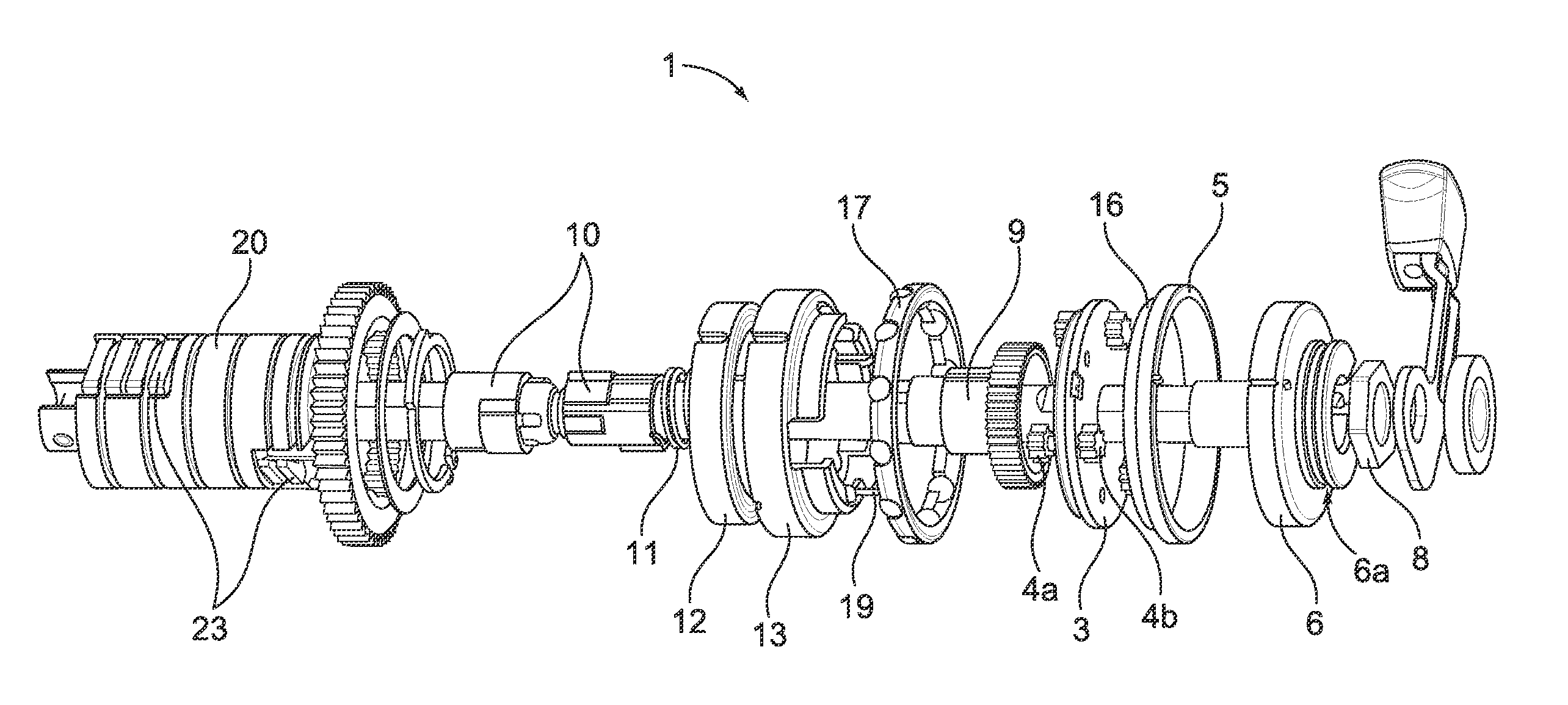
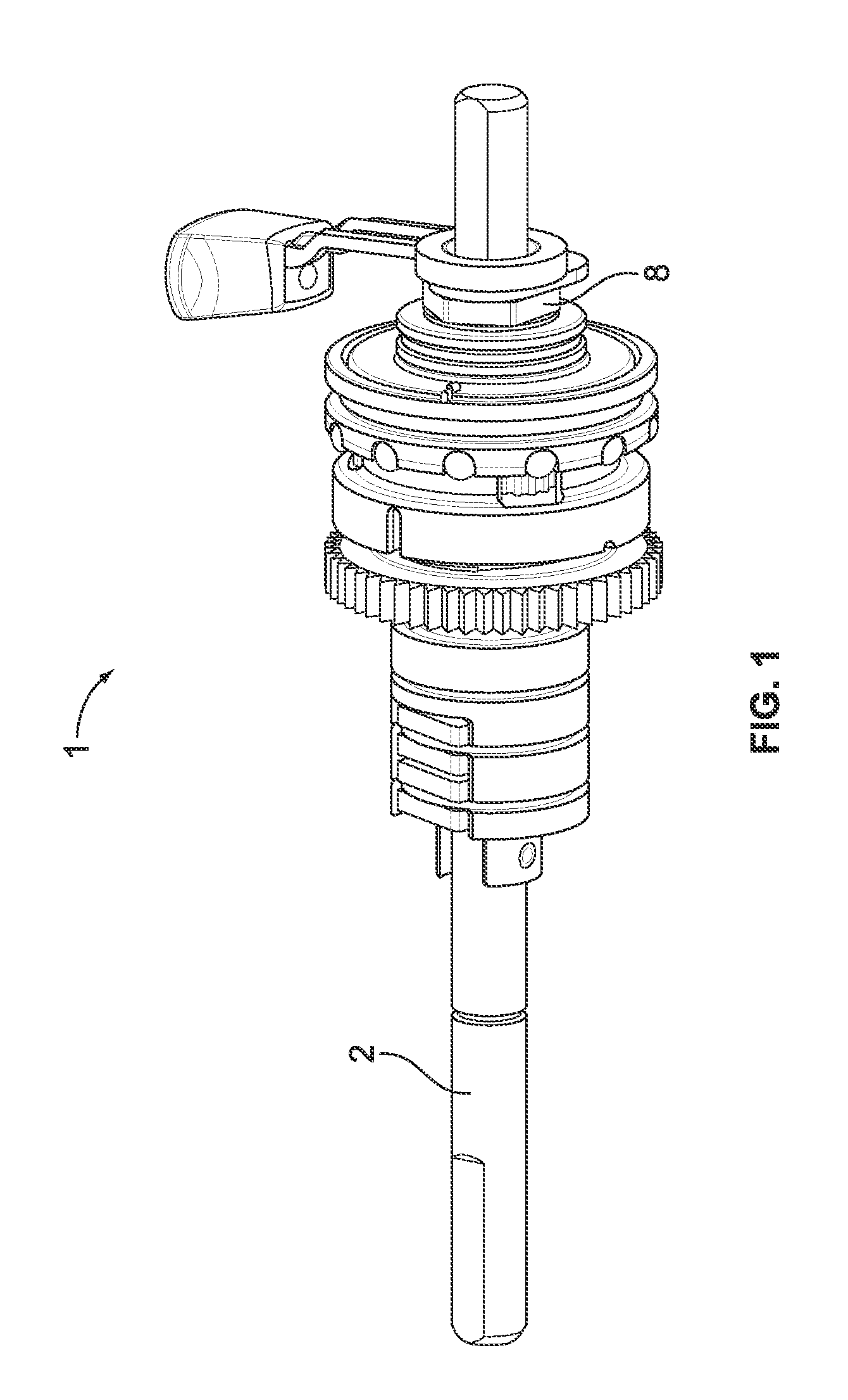
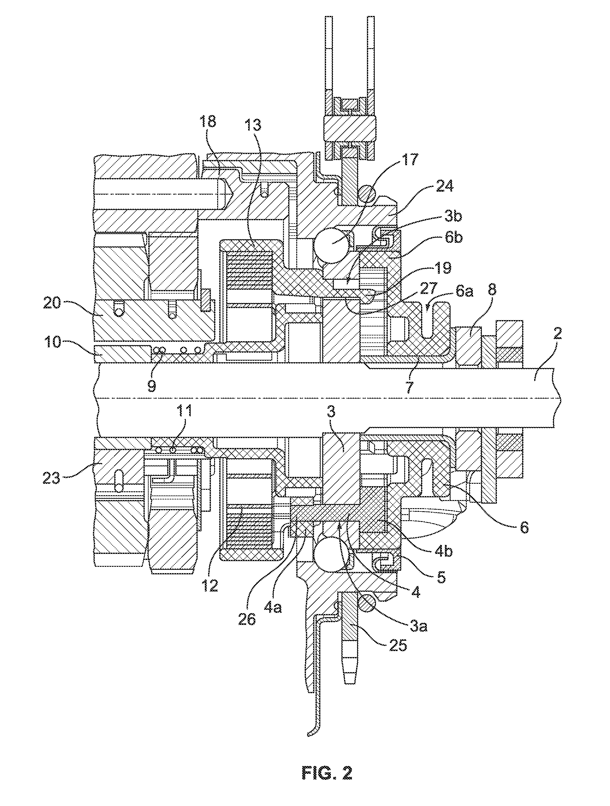
[0028]The components mounted on the axle of the hub axle of a cross sectional view of the operating mechanism according to the invention for a multispeed gear hub are represented generally in FIG. 1 and shown in detail in FIG. 2.

[0029]FIG. 2 shows a cross sectional view of the operating mechanism (1) for rotational switch introduction of a multi-speed hub, which is arranged at the end concentrically around a hub axle (2). The operating mechanism (1) includes in detail a fixed cone (3), several gear shafts (4) each shaft with outer (4a) and inner cog wheels (4b), a sealing ring (5), an operating sleeve (6), a securing sleeve (7), an axle nut (8), a transmission shaft (9), a ret


PUM


Abstract

An operating mechanism by which the linear movement of a gearshift cable is converted into a rotational movement of an operating sleeve and transmitted to the interior of a bicycle multispeed gear hub.

Description


Claims


Application Information

Patent Timeline
Owner SRAM
Why Eureka
Try Eureka