Vibration damping apparatus, electric actuator driving apparatus and vehicle

a technology of vibration damping and electric actuator, which is applied in the direction of motor/generator/converter stopper, dynamo-electric converter control, instruments, etc., can solve the problems of harmonic generation, affecting the reliability and durability of the system, and affecting the performance of the system, so as to avoid harmonic generation, effectively enhance the reliability and durability, and effectively prevent the collision of the movable elemen

Active Publication Date: 2012-11-22
SINFONIA TECHNOLOGY CO LTD
View PDF1 Cites 9 Cited by
  • Summary
  • Abstract
  • Description
  • Claims
  • Application Information

AI Technical Summary

Benefits of technology

The present technology describes how to improve the performance of electronic devices by reducing interference between moving parts caused during operation without causing damage. It involves detecting over-current instructions and adjusting certain parameters based on their impacts instead of just giving them upward. This helps reduce collisions and breaks down components more efficiently than traditional methods. Additionally, this system uses advanced techniques to rewrite signals before they reach us, further improving its efficiency. Overall, these technical improvements help make sure things work properly even if there're too much power usage compared to what was previously needed.

Problems solved by technology

This patents describes different techniques aim at reducing collisional damage caused when two moving parts come into contact during use of an electronic control system called an electro-magnetic valve. These methods include restricting power supply signals supplied to certain components while avoiding excessive force due to impact between these movements. Additionally, they involve monitoring and detecting any changes made over time without interrupting normal operations. However, existing solutions have limitations: limited protection against accidental failures; limitation of applying corrective currents only if necessary but cannot guarantee complete safety measures.

Method used


Image

  • Vibration damping apparatus, electric actuator driving apparatus and vehicle
  • Vibration damping apparatus, electric actuator driving apparatus and vehicle
  • Vibration damping apparatus, electric actuator driving apparatus and vehicle

Examples


Embodiment Construction

[0050]In the following, a vibration damping apparatus and an electronic actuator driving apparatus of the present embodiment which are applied to a vehicle are described with reference to FIGS. 1 to 10. The present embodiment corresponds to the first aspect of the disclosure and the second aspect of the disclosure.

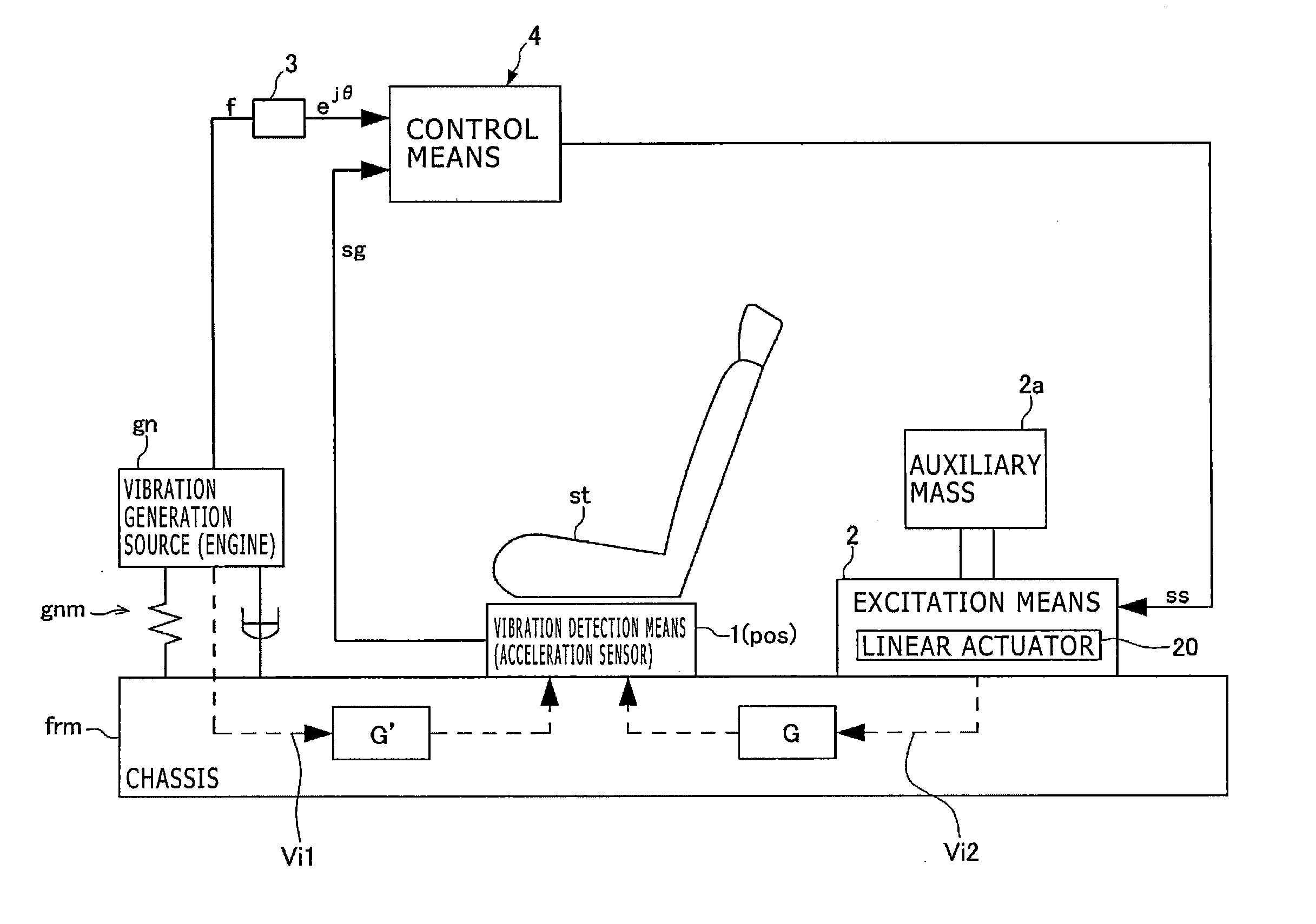
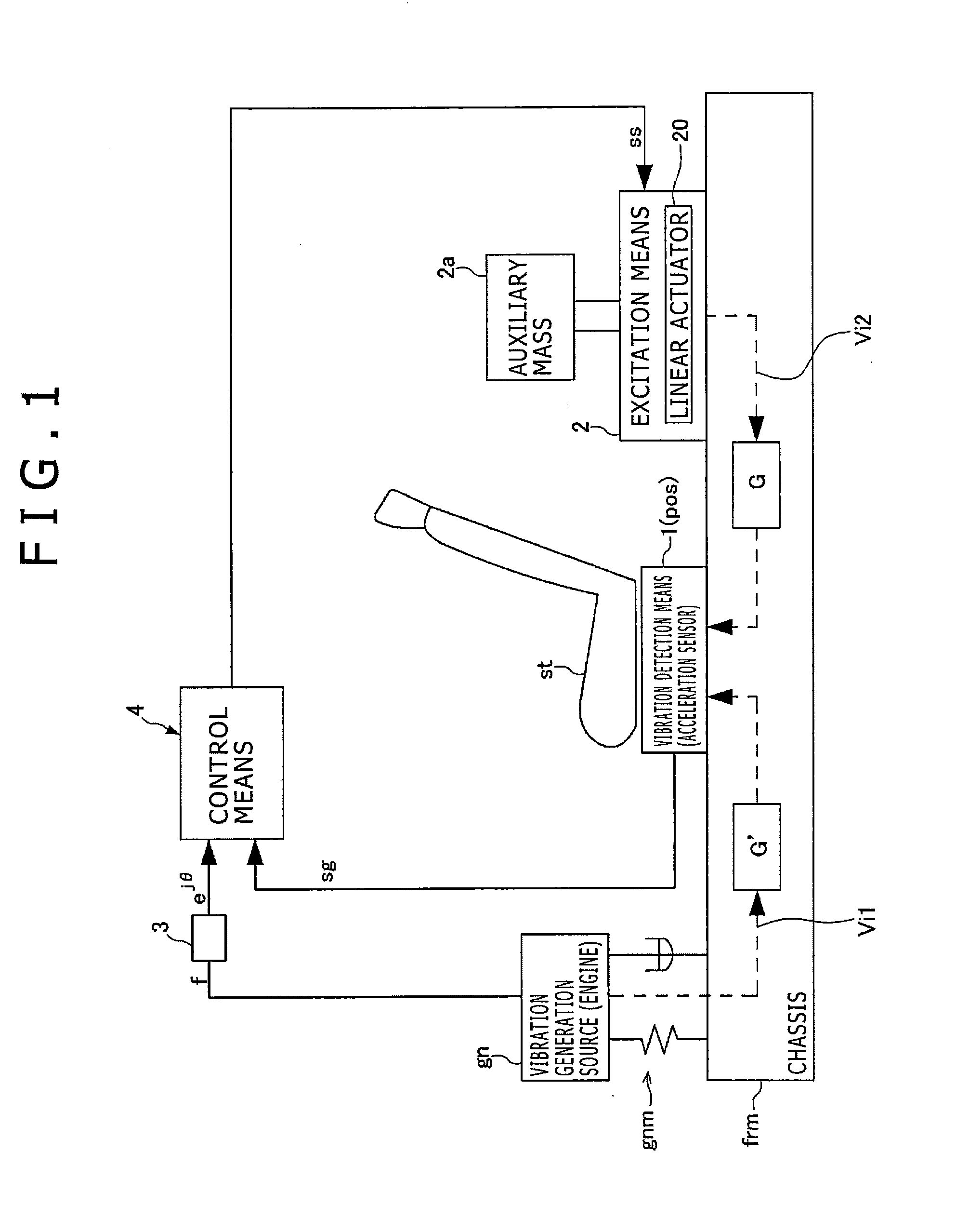
[0051]When the electric actuator driving apparatus of the present embodiment produces a driving instruction which is a periodic signal and inputs the driving instruction to drive an electric actuator, it produces a driving instruction signal based on an instruction vector having amplitude information and phase information corresponding to an amplitude and a phase of the driving instruction signal and is incorporated in the vibration damping apparatus. The vibration damping apparatus of the present embodiment is incorporated in a vehicle such as an automobile as shown in FIG. 1, and has vibration detection means 1 such as an acceleration sensor and so forth provided at a posit


PUM


Abstract

A vibration damping apparatus including reference wave production section that produces a reference wave; a fundamental order adaptive algorithm block that calculates fundamental order adaptive filter factors from a vibration detection signal and the reference wave and produces a fundamental order vibration damping current instruction; an amplitude detection section that calculates a peak current value of the fundamental order vibration damping current instruction; and a fundamental order current excess detection section that derives a fundamental order current upper limit value from the fundamental frequency to produce a fundamental order current upper limit excess signal that is output to the fundamental order adaptive algorithm block, which revises the fundamental order adaptive filter factors in a direction in which the vibration damping current instruction is limited within a range.

Description


Claims


Application Information

Patent Timeline
Owner SINFONIA TECHNOLOGY CO LTD
Why Eureka
Try Eureka