Electronic duplexer

Inactive Publication Date: 2013-01-17
TELEFON AB LM ERICSSON (PUBL)
View PDF4 Cites 17 Cited by
  • Summary
  • Abstract
  • Description
  • Claims
  • Application Information

AI Technical Summary

Benefits of technology

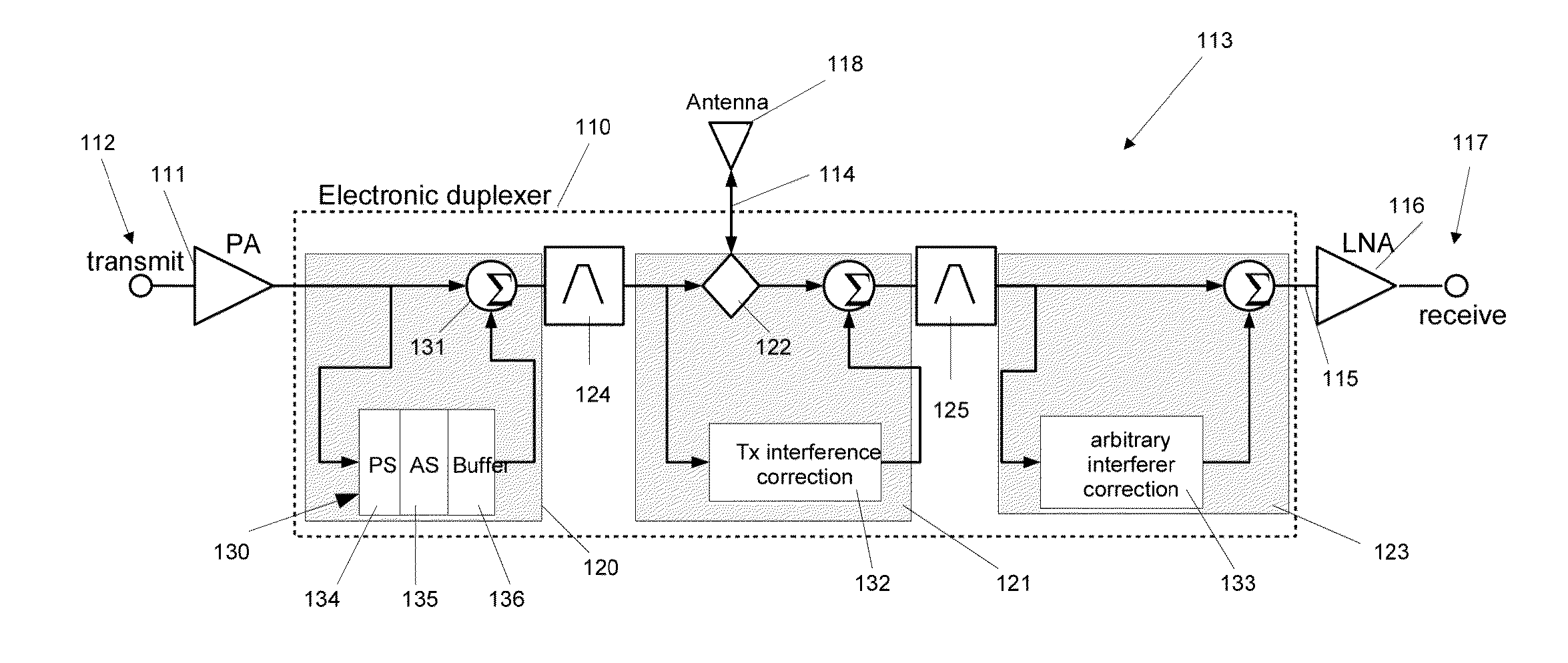
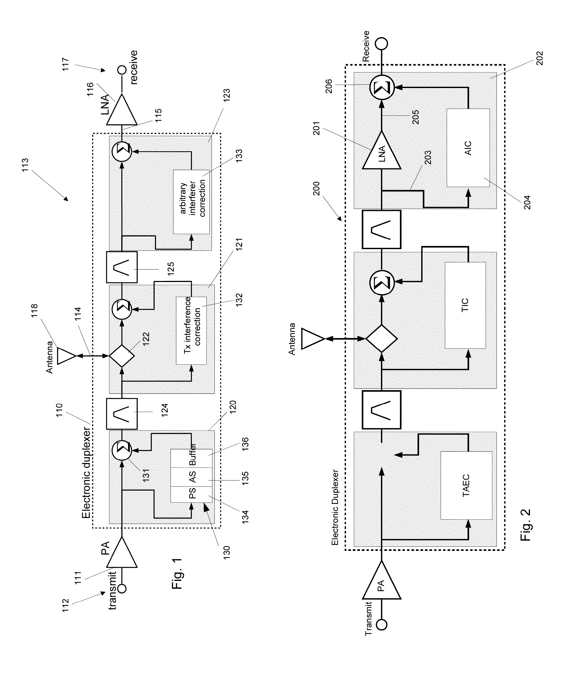
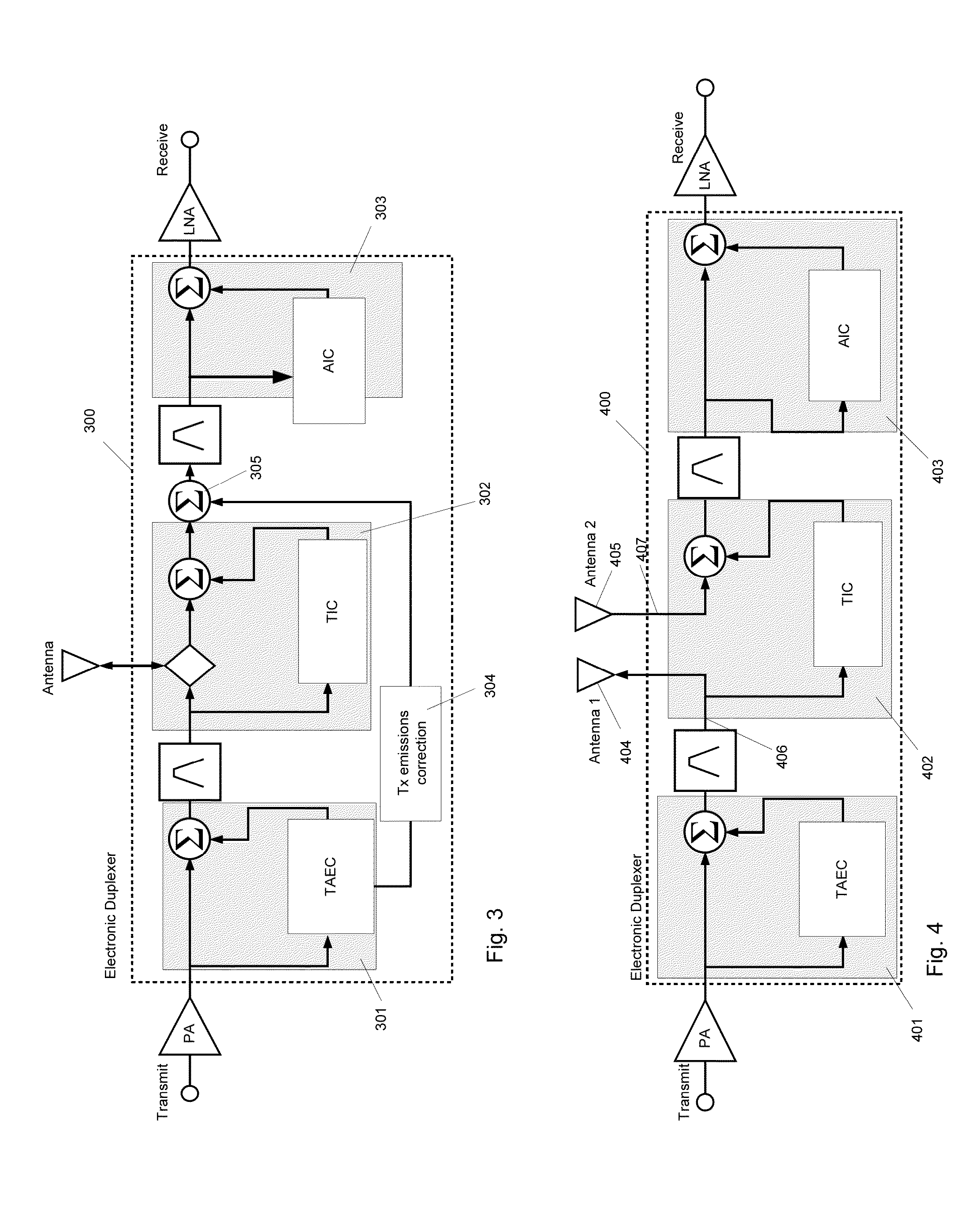
[0007]The present invention overcomes the problems of the prior art by providing an electronic duplexer which is able to correct for broadband emission noise introduced by power amplifier, reduce interference caused by the transmit signal and observed in the receive path and identify and correct interference signals other than those created by the transmit signal. In particular, the invention provides an electronic duplexer for sharing at least one antenna between at least one transmitter in a transmit path and at least one receiver in a receive path. The electronic duplexer comprises an electronic duplexer input for receiving at least one input transmit signal from the transmit path and an electronic duplexer output for providing at least one desired output signal to the receive path. An antenna interface has a transmit portion for transmitting an at least one desired transmit signal over the at least one antenna and a receive portion for receiving an at least one receive signal over the at least one antenna. A transmit antenna emissions correction circuit has an input coupled to the antenna interface. The transmit antenna emissions correction circuit correcting broadband noise emissions from the transmit path in the at least one input transmit signal thereby providing an at least one corrected transmit signal. A transmit interference correction circuit has an input coupled to the transmit portion of the antenna interface and an output coupled to the receive portion of the antenna interface. The transmit interference correction circuit correcting interference of the at least one transmit signal in the receive path thereby providing a first at least one corrected receive signal. An arbitrary interferer correction circuit has an input coupled to the receive portion of the antenna interface and an output coupled to the electronic duplexer output. The arbitrary interferer correction circuit correcting interference of signals other than the broadband noise emissions from the transmit path and the interference of the at least one transmit signal in the receive path thereby providing the at least one output receive signal.

Problems solved by technology

For example, a number of limitations and practical challenges need to be overcome in the areas of high-power filtering, frequency agility, linearity and low insertion loss.
However, given the broad and unpredictable range of feeder cable lengths for each base station deployment, it would be impractical to attempt to control the delay mismatch variation of a feedforward cancellation arrangement with a feedforward path between the transmit and receive ports of the antenna coupling network.
Furthermore, even if the feedforward path coax delay line was implemented with smaller gauge cable, the volume occupied by the delay line could easily exceed that of a typical duplexer for large towers (long feeder lengths) and occupy a significant portion of the base station footprint.
Additional factors that limit the performance of feedforward cancellation circuits over wide frequency bands is the delay mismatch between the main path and the cancellation path and the inherent frequency dependence of circuit components in terms of amplitude and phase ripple over a given frequency range.
Conventional filter duplexers can be used to isolate the transmit and receive circuitry but unusually strong, close-in interferers may be very difficult to deal with.
Additionally, conventional filters are not easily adaptable to new operating frequencies.
Existing adaptive/agile/electronic duplexer designs only address one of the noise or emissions problems.
For these reasons, traditional feedforward cancellation arrangements are not sufficient to implement a frequency agile duplexer architecture, especially in a radio platform which can be reconfigured to operate at high power levels in multiple modes and in multiple frequency bands.

Method used


Image

  • Electronic duplexer
  • Electronic duplexer
  • Electronic duplexer

Examples


Example

[0037]FIG. 5 shows a block diagram of an electronic duplexer according to a fifth embodiment of the invention. This embodiment is similar to the first embodiment of FIG. 1, however, in FIG. 5, the main path filters have been removed such that the radio system relies on the correction abilities of the FFCLs to provide all the signal rejection required to meet the radio system operational requirements. The lack of filters in the main path provides the potential for maximum frequency agility.

Example

[0038]FIG. 6 shows a block diagram of a sixth embodiment of the invention. This embodiment illustrates the use of FFCLs in a general N×M MIMO system with multiple (N) transmitters and multiple (M) receivers.

[0039]Each TX branch has its own TAEC and each RX branch has it's own AIC. In the most general case of N×M MIMO (N TX, M RX) then a TIC is needed for each TX to every RX.


PUM


Abstract

The present disclosure relates to an electronic duplexer for at least one transmit path and at least one receive path in a radio system where the transmit and receive paths share the use of at least one antenna. A first feedforward correction loop is used to correct broadband noise emissions (that do not include linearity related close-in emissions) from the power amplifier in a radio system. A second feedforward correction loop is used to reduce the interference of the transmit signal in the receive path. A third feedforward correction loop is used to identify interference signals other than the transmit signal and correct those additional interferers.

Description


Claims


Application Information

Patent Timeline
Owner TELEFON AB LM ERICSSON (PUBL)
Why Eureka
Try Eureka