Unipolar, bipolar and hybrid MIMO antennae
a hybrid and antenna technology, applied in the field of wireless communication, can solve the problems of difficult to meet the requirement of a low power consumption, and achieve the effects of easy integration together, increased isolation degree, and reduced power consumption
- Summary
- Abstract
- Description
- Claims
- Application Information
AI Technical Summary
Benefits of technology
Problems solved by technology
Method used
Image

Examples
embodiment i
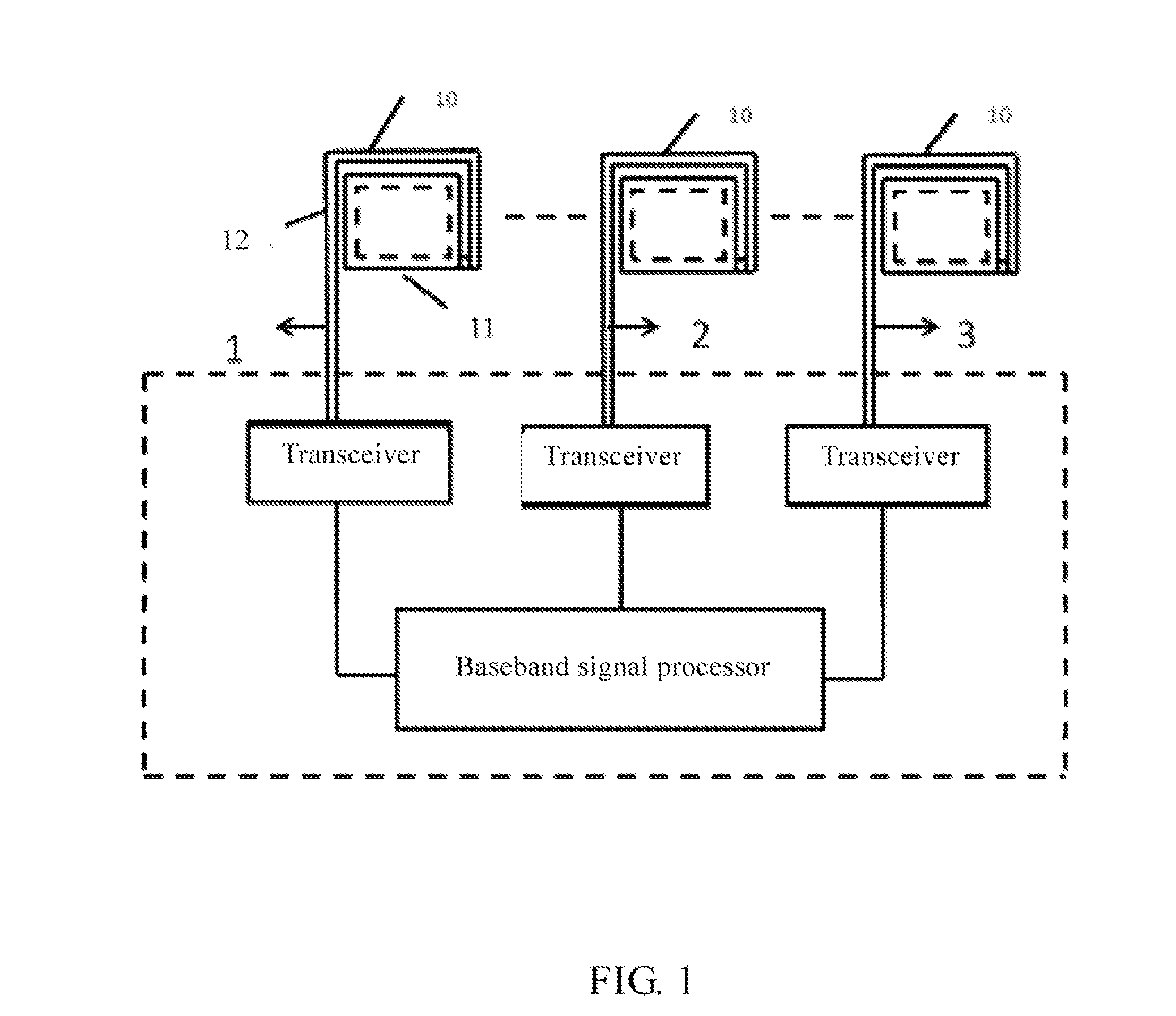
[0043]As shown in FIG. 1, the unipolar MIMO antenna in this embodiment consists of a plurality of unipolar RF antennae, each of which comprises a metal sheet 11 and a feeder line 12. The feeder line 12 is fed into the metal sheet 11 in a signal coupling manner. Metal microstructures of the unipolar RF antennae constituting the unipolar MIMO antenna may be all the same as each other or be different from each other. Each of the unipolar RF antennae is connected to one transceiver, and all of the transceivers are connected to one baseband signal processor.
[0044]A medium for disposing the metal sheet and the feeder line thereon in the present disclosure may be air, ceramic or a medium substrate. A short-circuit point for the feeder line and the metal microstructure may be located at any position on the metal microstructure. For the unipolar MIMO antenna of this embodiment, the operating frequency thereof may be tuned by adjusting the feed-in coupling manner of the feeder line, the topology
embodiment ii
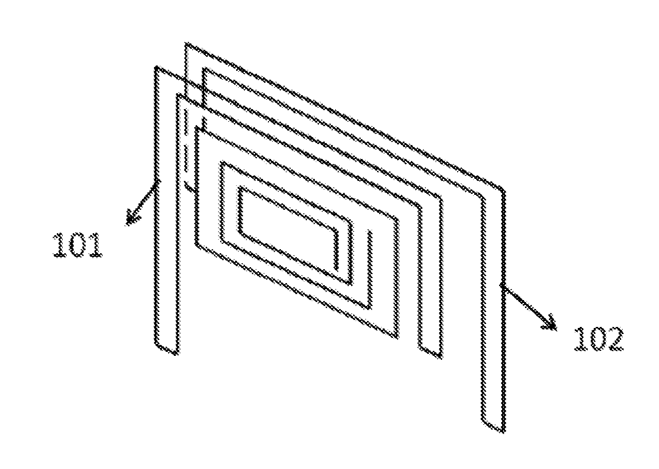
[0051]As shown in FIG. 6 and FIG. 7, in this embodiment, the bipolar MIMO antenna consists of a plurality of bipolar RF antennae 20, and each of the bipolar RF antennae 20 comprises a feeder line 101, a grounding unit 102, and two metal sheets having a topology structure. The two metal sheets are disposed in parallel with each other. The feeder line 101 feeds a baseband signal into one of the metal sheets, and the grounding unit 102 is connected to the other of the metal sheets. Moreover, the two metal sheets may be each formed with a metallized through-hole, which is used to short the metal sheets together. Metal microstructures of the bipolar RF antennae constituting the bipolar MIMO antenna may be all the same as each other or be different from each other. Each of the bipolar RF antennae is connected to one transceiver, and all of the transceivers are connected to one baseband signal processor.
[0052]The feeder line and the grounding unit are viewed as two pins of an RF-chip small an
embodiment iii
[0058]As shown in FIG. 11, in this embodiment, the hybrid MIMO antenna consists of at least one unipolar RF antenna 10 and at least one bipolar RF antenna 20. Metal microstructures of the RF antennae constituting the hybrid MIMO antenna may be all the same as each other or be different from each other. Each of the RF antennae is connected to one transceiver, and all of the transceivers are connected to one baseband signal processor.
[0059]The characteristics of the at least one unipolar RF antenna and the at least one bipolar RF antenna in this embodiment are identical to those of the RF antennae in the embodiment I and the embodiment II, and thus will not be further described herein.
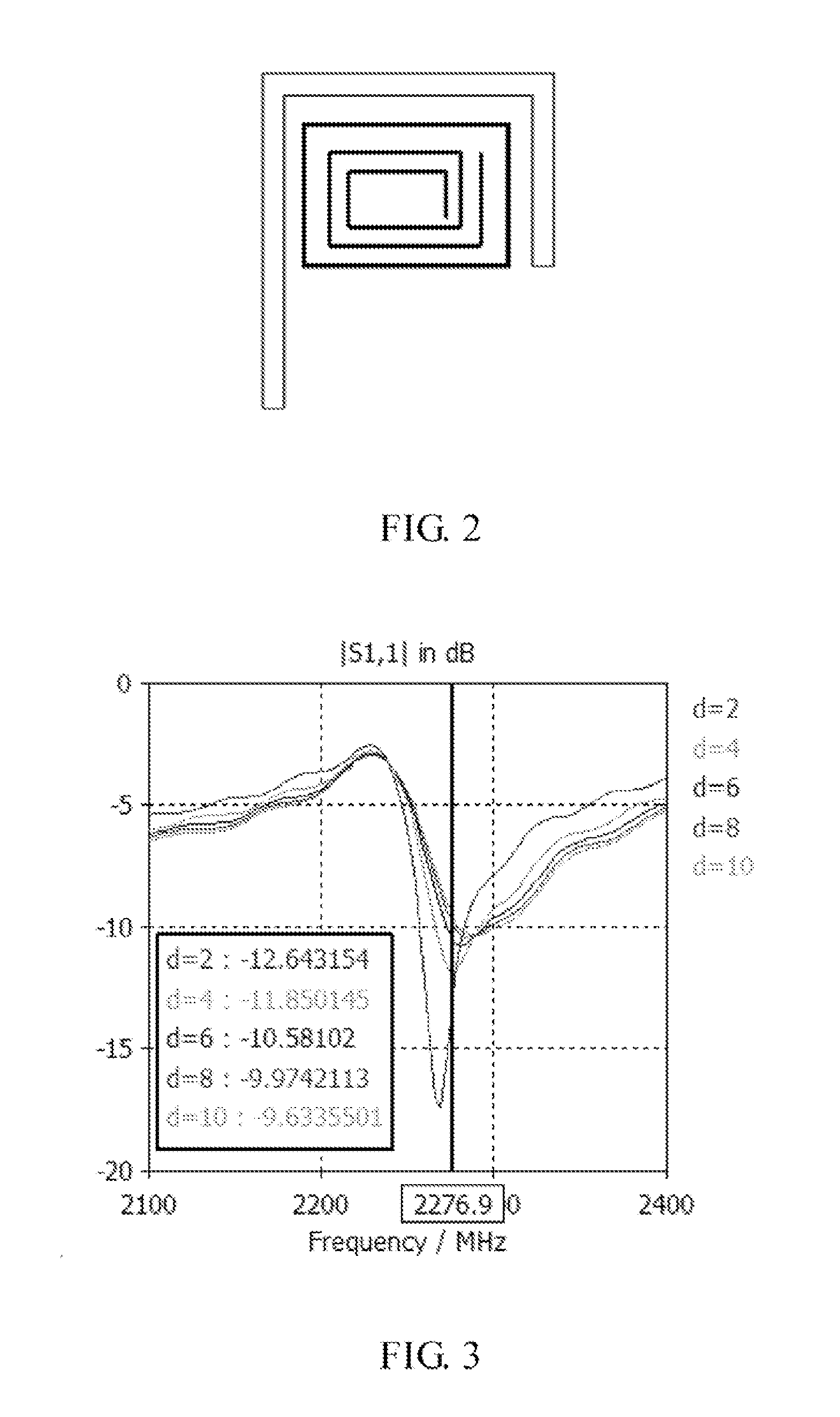
[0060]Additionally, the structure of the metal microstructures is not limited to what shown in FIG. 2 and FIG. 7, but may also be of other structures such as a split ring resonator structure, a complementary spiral structure, a split spiral ring structure, a dual split spiral ring structure, a complementary
PUM
 Abstract
Description
Claims
Application Information
 - R&D Engineer
- R&D Manager
- IP Professional
- Industry Leading Data Capabilities
- Powerful AI technology
- Patent DNA Extraction
Browse by: Latest US Patents, China's latest patents, Technical Efficacy Thesaurus, Application Domain, Technology Topic.
© 2024 PatSnap. All rights reserved.Legal|Privacy policy|Modern Slavery Act Transparency Statement|Sitemap