Drive transmission device, sheet feeder, and image forming apparatus

a transmission device and transmission device technology, applied in mechanical devices, transportation and packaging, gearing, etc., can solve the problems of increasing the device size and complicating the device structur

Active Publication Date: 2013-05-02
RICOH KK
View PDF4 Cites 15 Cited by
  • Summary
  • Abstract
  • Description
  • Claims
  • Application Information

AI Technical Summary

Benefits of technology

The present invention relates to a sheet feeder that includes two reversed feed rollers. One of them can also have a downstream reverse feed roller. A controller sends signals to both rollers to adjust their speed accordingly. This allows for more precise timing between the rollers' operations.

Problems solved by technology

The technical problem addressed in this patent is how to efficiently control the movement of a roller member in a driving apparatus that can transfer power between different modes without increasing its size and complexity.

Method used


Image

  • Drive transmission device, sheet feeder, and image forming apparatus
  • Drive transmission device, sheet feeder, and image forming apparatus
  • Drive transmission device, sheet feeder, and image forming apparatus

Examples


Embodiment Construction

[0045]In describing the embodiments illustrated in the drawings, specific terminology is adopted for the purpose of clarity. However, the disclosure of the present invention is not intended to be limited to the specific terminology so used, and it is to be understood that substitutions for each specific element can include any technical equivalents that operate in a similar manner and achieve a similar result.

[0046]Referring now to the drawings, wherein like reference numerals designate identical or corresponding parts throughout the several views, a printer according to an embodiment of the present invention (hereinafter referred to as the printer 100) will be described.

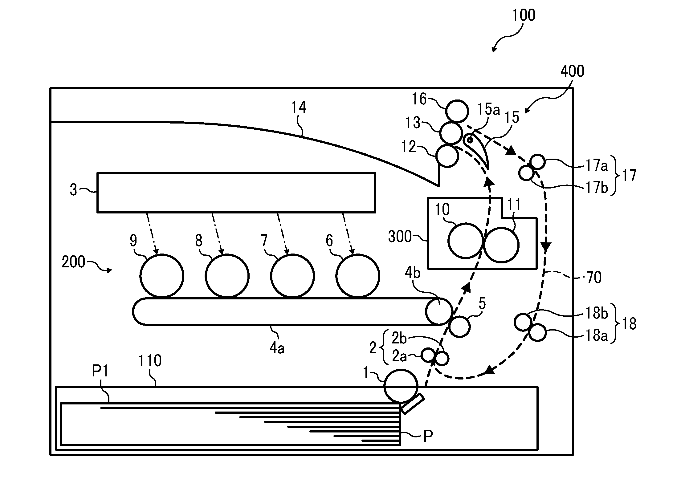
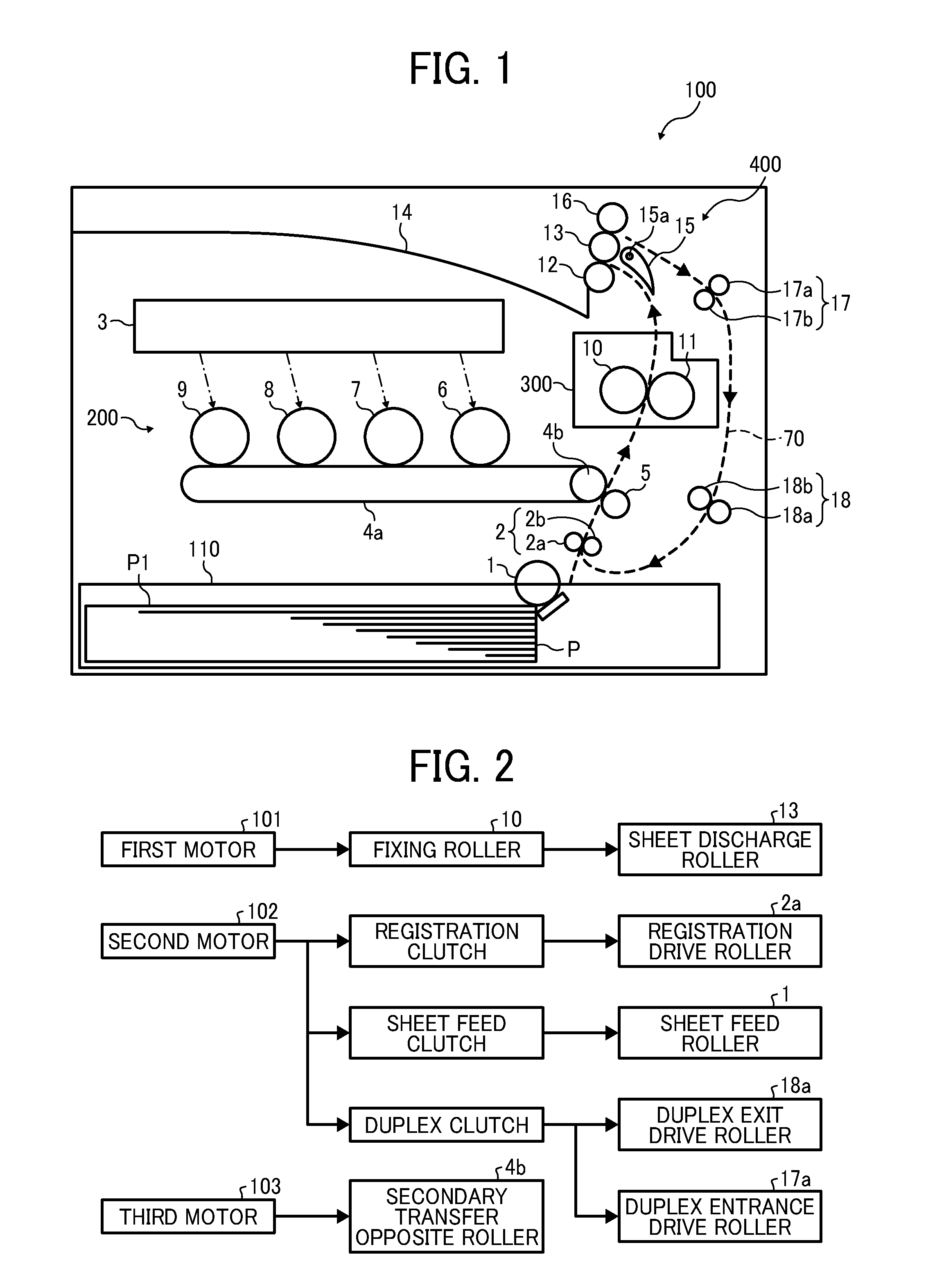
[0047]FIG. 1 is a schematic configuration diagram of the printer 100. The application of a drive transmission device according to an embodiment of the present invention is not limited to the type of image forming apparatus illustrated in FIG. 1 (i.e., the printer 100) or the type of sheet feeder illustrated in FIG. 1 (


PUM

PropertyMeasurementUnit
Timeaaaaaaaaaa
Shapeaaaaaaaaaa

Abstract

A drive transmission device includes a gear train and a movable gear locking device. The gear train transmits rotational drive to a drive target, and includes a first gear train forming a first transmission path for transmitting the drive to the target, a second gear train forming a second transmission path for transmitting the drive to the target as drive opposite in rotation direction to the drive transmitted by the first gear train, and a movable gear movable between a first drive transmission position whereat the movable gear forms a part of the first gear train to transmit the drive to the target and a second drive transmission position whereat the movable gear forms a part of the second gear train to transmit the drive to the target. The movable gear locking device locks the movable gear at an idle position.

Description


Claims


Application Information

Patent Timeline
Owner RICOH KK
Why Eureka
Try Eureka