Automatic tracking camera system

Active Publication Date: 2013-05-16
CANON KK
View PDF3 Cites 7 Cited by
  • Summary
  • Abstract
  • Description
  • Claims
  • Application Information

AI Technical Summary

Benefits of technology

[0008]The present invention provides an automatic tracking/image pickup apparatus capable of performing an automatic tracking/image p

Problems solved by technology

However, in order to perform the automatic tracking/image pickup operation through use of the image recognition technology, the object needs to appear within the range of the camera, otherwise the automatic tracking/image pickup operation cannot be started.
In particular, in a case of picking up an image of landing of an aircraft, the runway and angle for the landing may be changed depending on meteorological condition

Method used


Image

  • Automatic tracking camera system
  • Automatic tracking camera system
  • Automatic tracking camera system

Examples


embodiment

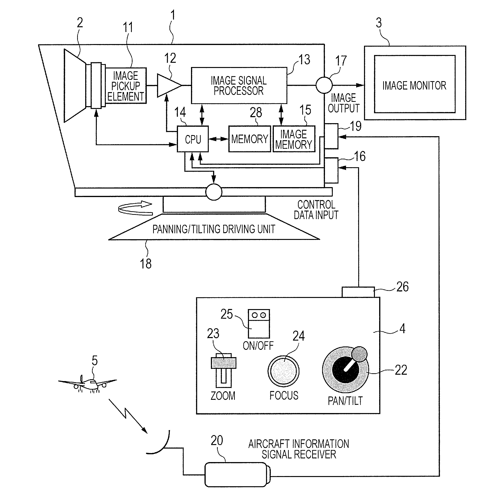
[0016]FIG. 1 is a system diagram illustrating an automatic tracking camera system according to an embodiment of the present invention by taking, as an example, a platform camera, which is operated in a remote place as an image pickup apparatus having a tracking function. Referring to FIG. 1, a system overview is described.

[0017]As illustrated in FIG. 1, the automatic tracking camera system of the present invention includes an image pickup unit, which includes a lens apparatus 2 and an image pickup apparatus including an image pickup element 11, a platform camera 1, which has the image pickup unit mounted thereto and is operated in a remote place, an image monitor 3 for displaying an image picked up by the platform camera 1, an operation apparatus 4 for operating the platform camera 1, and an aircraft information signal receiver 20 for receiving an aircraft information signal (object information signal) of an aircraft 5 as an object.

[0018]In the platform camera 1, the object image picke


PUM


Abstract

An automatic tracking camera system includes: an image pickup unit; a driving unit for rotating the image pickup unit in panning or tilting direction; a signal receiver for receiving an object information signal; an image signal processor for recognizing an object in an image and detecting motion of the object in the image; a controller for controlling the image pickup unit, the driving unit, and the image signal processor; and a memory for storing, for each passageway, standby positions at which the image signal processor detects the object. The controller calculates an approaching passageway and angle of the object; selects a corresponding standby position from the standby positions stored in the memory; drives the driving unit and a lens apparatus to the standby position; and controls, when the image signal processor recognizes the object, the driving unit and the lens apparatus to automatically track the object based on detected information.

Description


Claims


Application Information

Patent Timeline
Owner CANON KK
Why Eureka
Try Eureka