Pneumatic Tire

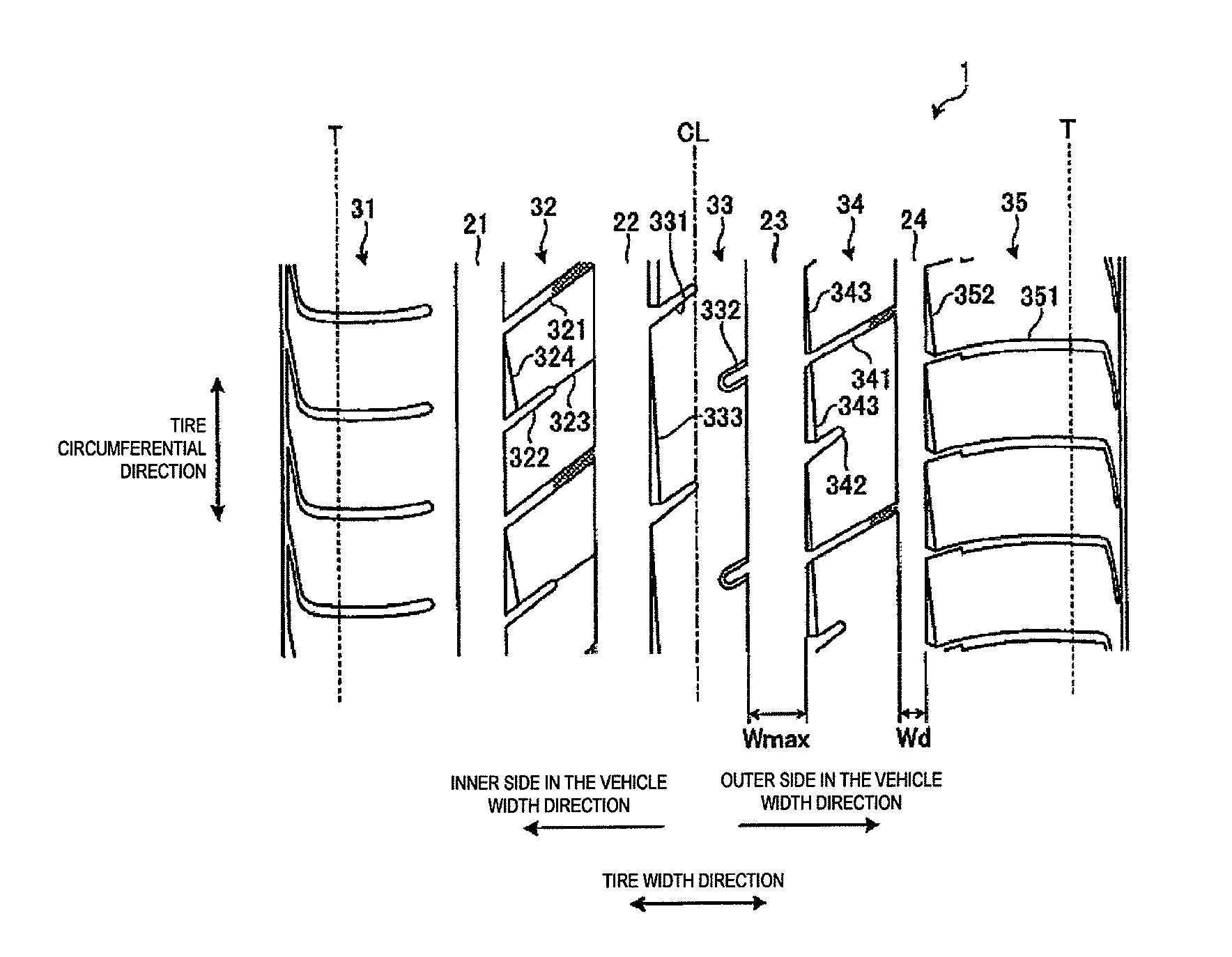
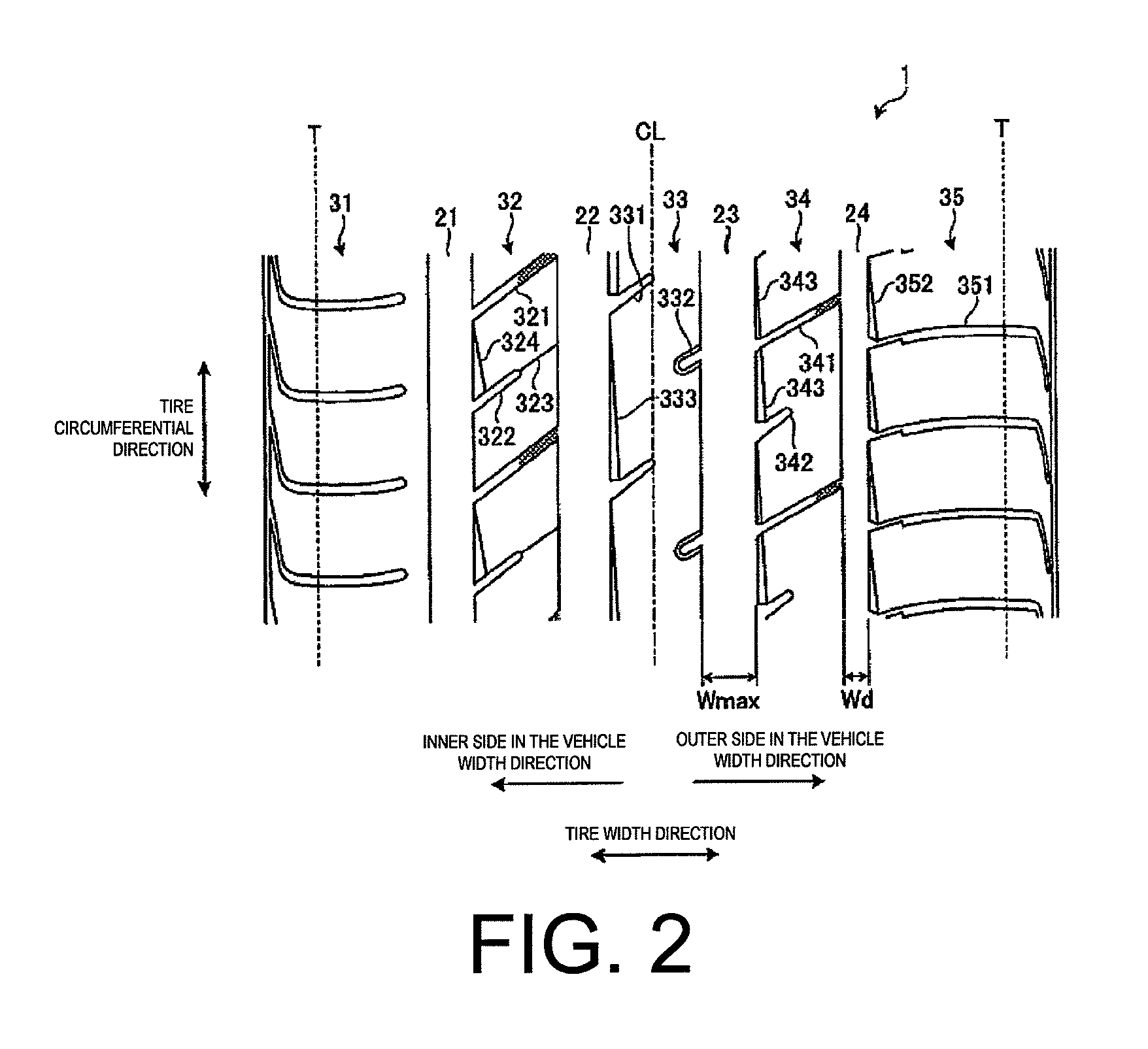
a technology of pneumatic tires and spherical plates, which is applied in the direction of vehicle components, non-skid devices, transportation and packaging, etc., can solve the problems of dry performance and wet performance of tires, and achieve the enhancement of water drainage properties of the region that has the inner side second land portion 32, the rigidity of the outer side second land portion 34

Active Publication Date: 2013-08-08
YOKOHAMA RUBBER CO LTD
View PDF4 Cites 15 Cited by
  • Summary
  • Abstract
  • Description
  • Claims
  • Application Information

AI Technical Summary

Benefits of technology

This patented design improves the durability and wetness characteristics of rubber tires used for vehicles. It achieves this through various technical features like increasing the number or depths of circularly shaped spaces between different parts inside the wheel's body cavity during use. These space areas help distribute moisture more evenly throughout the entirety of the car's interior. By doing these things, it enhances its ability to prevent damage caused by external factors including rainwater and snowfall. Overall, this design helps improve the overall functionality and safety of the rubber wheels in their respective applications.

Problems solved by technology

This patented technical solution describes how traditional methods used during manufacturing can improve the durability and stability of runaway vehicles' rubbery wheels due to their ability to absorb shocks without losing its effectiveness or causing damage from external factors like rainwater.

Method used


Image

  • Pneumatic Tire
  • Pneumatic Tire
  • Pneumatic Tire

Examples


examples

[0083]FIGS. 8a-8b include a table showing the results of performance testing of pneumatic tires according to embodiments of the present technology. FIGS. 9 and 10 are plan views illustrating treads of pneumatic tires of Conventional Examples 1 and 2.

[0084]In the performance testing, a plurality of mutually differing pneumatic tires were evaluated for (1) dry performance, and (2) wet performance (see FIGS. 8a-8b). In the performance tests, pneumatic tires with a tire size of 275 / 35R20 were assembled on a rim having a rim size of 20×9JJ (OE designated standard rim); and an air pressure of 260 kPa and a maximum load defined by JATMA were applied to these pneumatic tires, The pneumatic tires were mounted on a full-size sedan (not of Japanese make) used as a test vehicle.

[0085](1) In the evaluations for dry performance, the test vehicle was driven at a speed of from 60 km / h to 100 km / h on a flat circuit test course. Then, the test driver performed a sensory evaluation regarding steeri


PUM


Abstract

A circumferential narrow groove of a pneumatic tire is disposed at a position that partitions an outer side second land portion and an outer side shoulder land portion. A center land portion is a rib that is continuous in a tire circumferential direction, and an inner side second land portion and the outer side second land portion are rows of blocks divided in the tire circumferential direction by pluralities of lug grooves. Additionally, a groove area ratio S2 of the center land portion, a groove area ratio SI of the inner side second land portion, and a groove area ratio S3 of the outer side second land portion have a relationship such that S2<S3<S1. Moreover, a groove width Wd of the circumferential narrow groove and a maximum groove width Wmax of the other three circumferential main grooves to have a relationship such that 3.1≦Wmax/Wd≦5.0.

Description


Claims


Application Information

Patent Timeline
Owner YOKOHAMA RUBBER CO LTD
Why Eureka
Try Eureka