Method for forming metal member on casing

Inactive Publication Date: 2014-01-16
APONE TECH
View PDF6 Cites 1 Cited by
  • Summary
  • Abstract
  • Description
  • Claims
  • Application Information

AI Technical Summary

Benefits of technology

[0014]By means of technical means of the present invention, the metal members such as an antenna member, a ground wire member, or an electromagnetic shielding member can be formed on a casing in a common manufacture procedure. Thus, the manufacture procedure is simplified, and the production speed is raised. Further, time for assembling is reduced due to the metal members is f

Problems solved by technology

Such producing way brings heavy and complicated manufacture proced

Method used


Image

  • Method for forming metal member on casing
  • Method for forming metal member on casing
  • Method for forming metal member on casing

Examples


Embodiment Construction

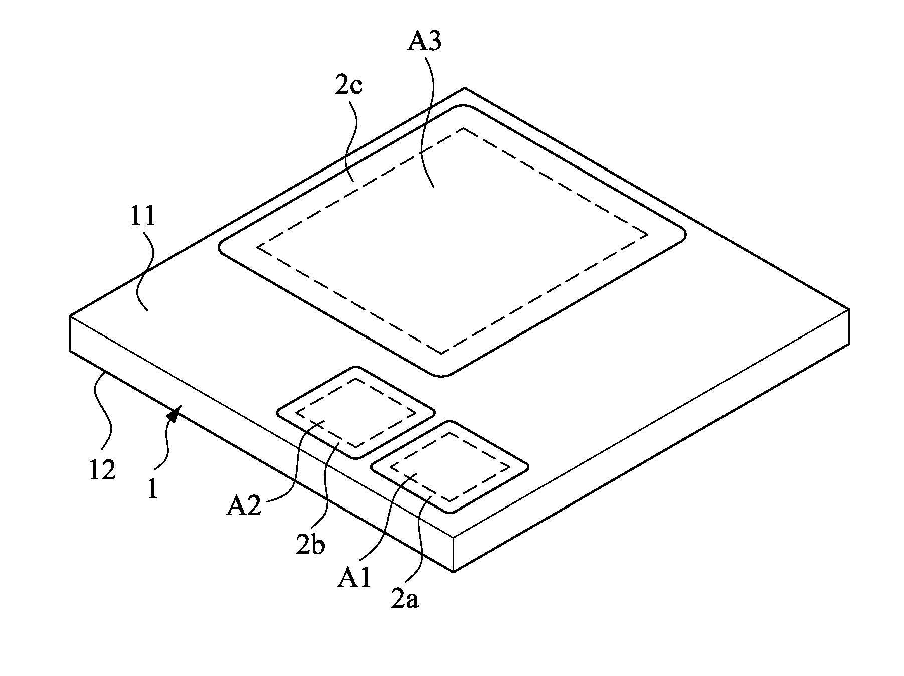
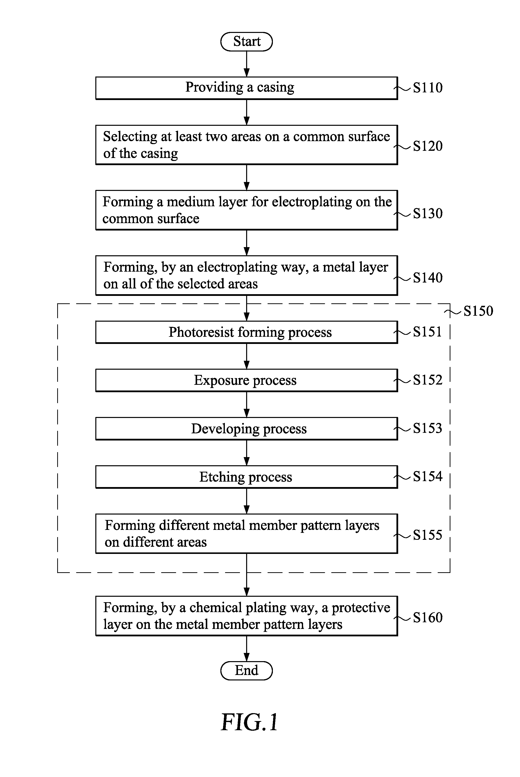
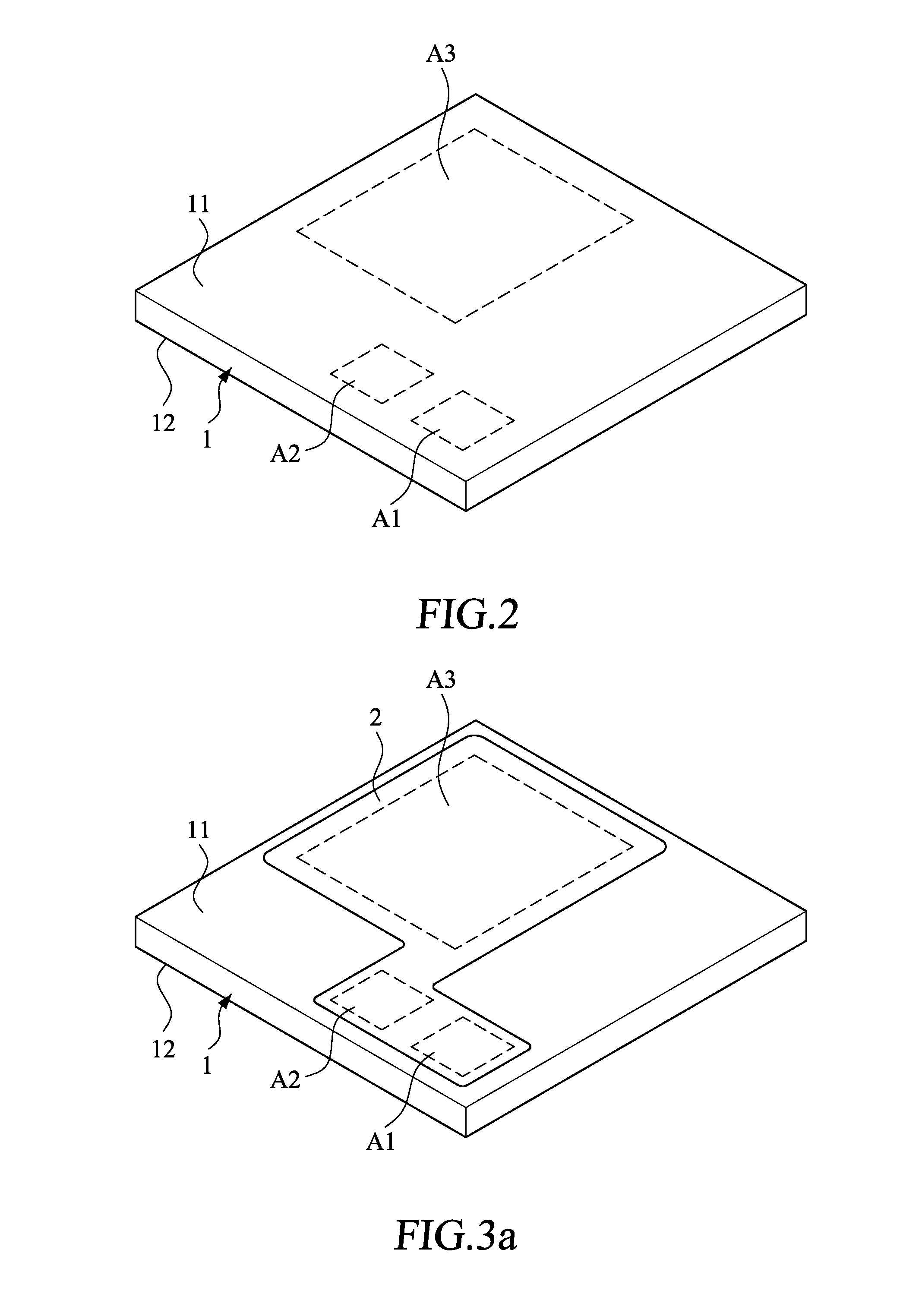
[0019]Please refer to FIGS. 1-4. FIG. 1 is a flow chat of a method for forming metal members on a casing of an embodiment according to the present invention; and FIGS. 2-4 are stereographic views illustrating forming metal members on a casing by the method according to the present invention.

[0020]Firstly, a casing 1 of an electron device is provided (step S110). As an example, the electron device (not shown) may be a notebook computer, a tablet computer, or a mobile phone. In this embodiment, the casing 1 is made of an insulating material, such as plastics.

[0021]Next, as shown in FIG. 2, at least two areas on a common surface of the casing 1 are selected (step S120). Generally, the casing 1 has an inner side surface 11 and an outer side surface 12, wherein the inner side surface 11 is referred to a surface which faces to the inner side of the electron device, and the outer side surface 12 is referred to a surface which faces to outside of the electron device. In this step, it is prefer


PUM

PropertyMeasurementUnit
aaaaaaaaaa

Abstract

A method for forming metal members on a casing, includes steps of providing the casing of an electron device; selecting at least two areas on a common surface of the casing; forming, by an electroplating way, a metal layer on all of the selected areas; and forming, by a patterning way, the metal layer respectively with different metal member pattern layers on different selected areas, wherein the metal member pattern layers are selected from the group consisting of an antenna member pattern, a ground wire member pattern, and an electromagnetic shielding member pattern, so as to use these members as an antenna member, a ground wire member, or an electromagnetic shielding member of the electron device.

Description


Claims


Application Information

Patent Timeline
Owner APONE TECH
Why Eureka
Try Eureka