Vehicle brake pressure controller

a brake pressure controller and brake pad technology, applied in the field of brake pressure controllers, can solve the problems of reducing the brake pressure between the brake pad and the disc rotor, contributing to the abrasion of the brake pad, and reducing the brake drag, so as to improve the brake feeling and reduce the brake drag

Active Publication Date: 2014-05-22
SUBARU CORP
View PDF3 Cites 6 Cited by
  • Summary
  • Abstract
  • Description
  • Claims
  • Application Information

AI Technical Summary

Benefits of technology

The technical effect of this patented solution described by the inventor relates to improving the feel of driving with reduced resistance during car stopping on roadways without adding extra components like the main hydraulic pump used in traditional systems. This makes it easier than usual because drivers can only step their foot off before they start releasing them again after getting into traffic safely.

Problems solved by technology

This technical problem addressed by this patented technology relating to conventional vehicular disk brakes involves generating friction during normal use without causing any issues such as degrading power or increasing wear on the brach pads due to their being separated from the wheel's surface. Additionally, current methods require multiple operations that increase complexity and costs associated therewith.

Method used


Image

  • Vehicle brake pressure controller
  • Vehicle brake pressure controller
  • Vehicle brake pressure controller

Examples


Embodiment Construction

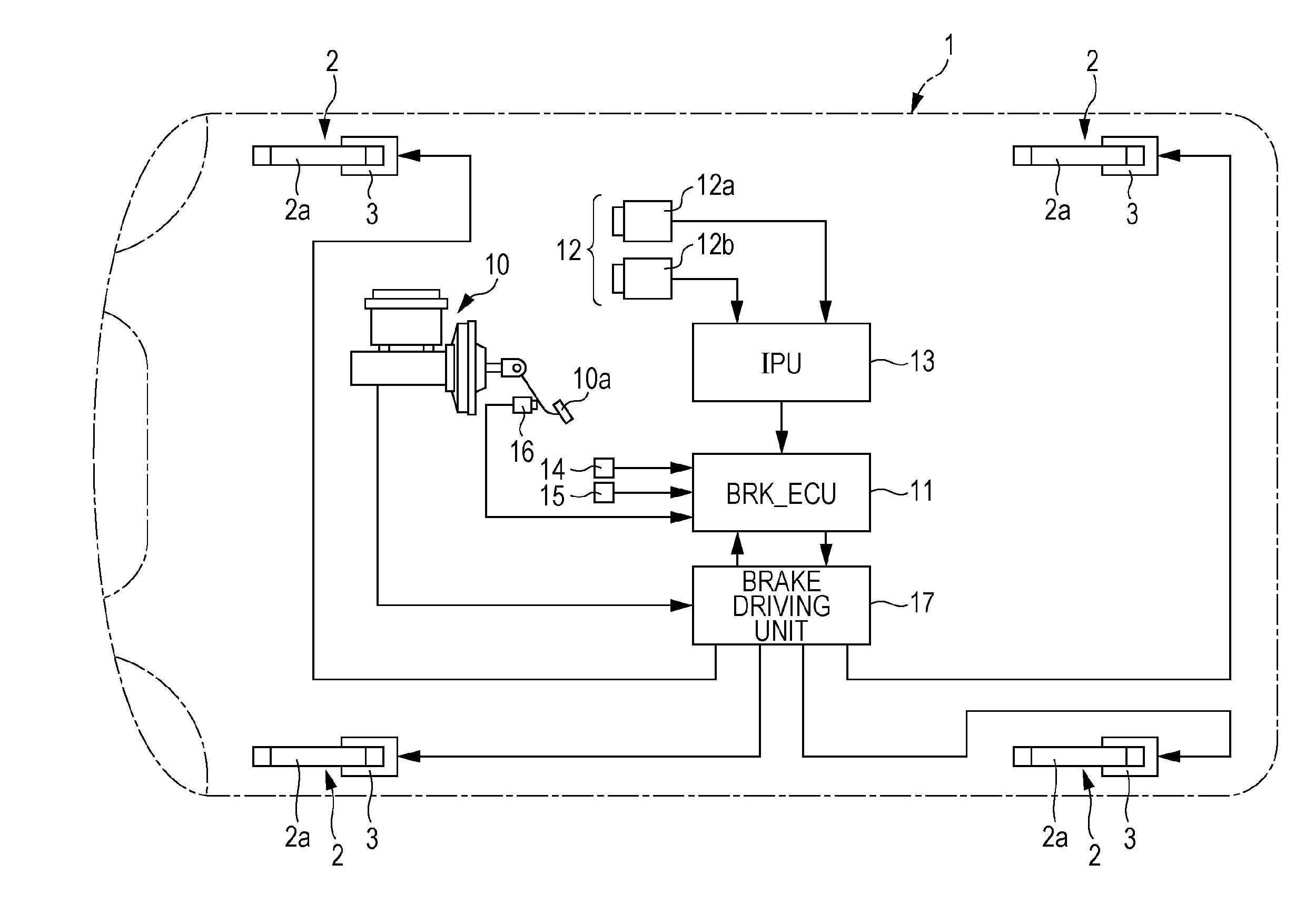
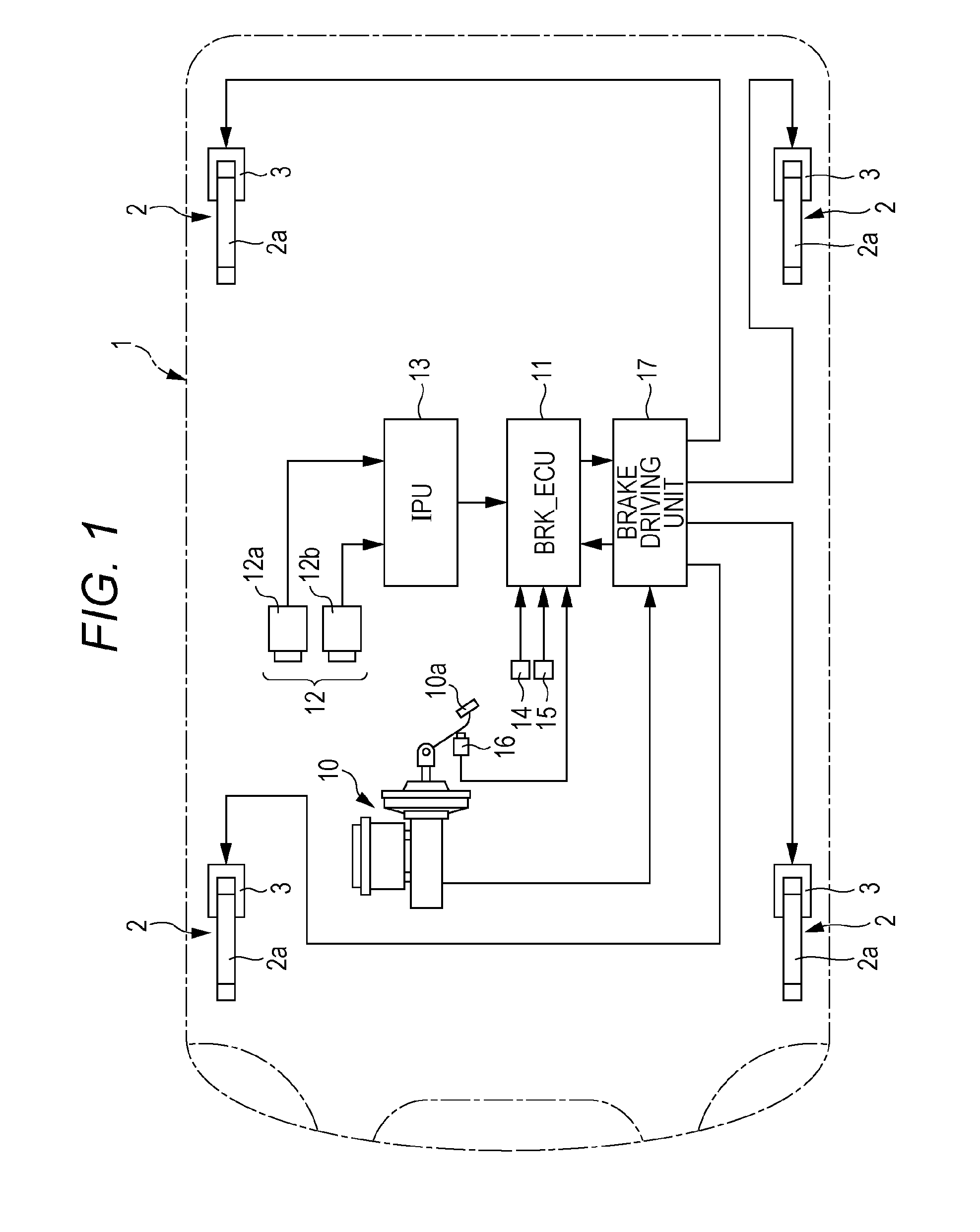
[0029]An example of the present invention will be described with reference to the drawings. As illustrated in FIG. 1, a disc brake 2 serving as the brake of the present invention is provided in each of four wheels of a vehicle (subject vehicle) 1. Each disc brake 2 has a disc rotor 2a and a caliper 3. The disc rotor 2a corresponds to the rotating member of the present invention and is fixed to a hub of each axle to integrally rotate. The caliper 3 is fixed to the vehicle body and is capable of nipping the disc rotor 2a.

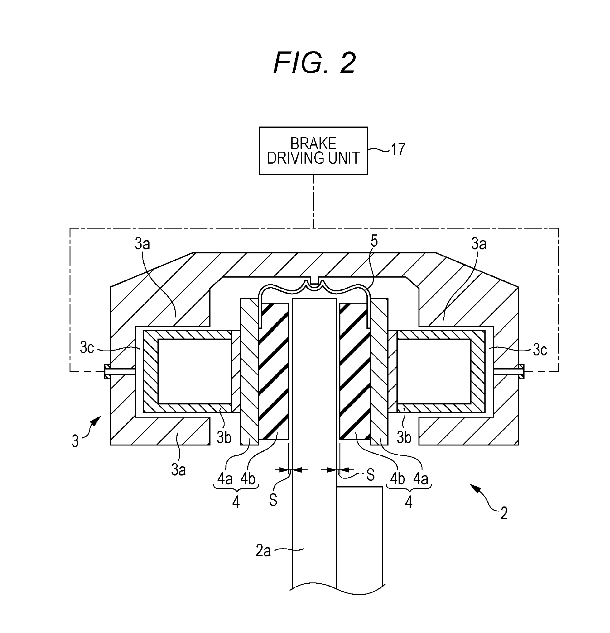
[0030]As illustrated in FIG. 2, the disc brake 2 of this example is an opposed-piston type: cylinders 3a are formed in surfaces opposed to the disc rotor 2a of the caliper 3, and a piston 3b is mounted on each cylinder 3a. A back metal 4a of a brake pad 4 is fixed to a front surface of the piston 3b, and a pad body 4b serving as the friction member is fixed to the back metal 4a.

[0031]When a brake fluid pressure is supplied from a later-described brake driving unit 17 t


PUM


Abstract

A brake controlling unit detects a brake actuation object based on images captured by a running environment recognizing unit and sets a target brake pre-pressure actuation distance based on a relative speed between the brake actuation object and a subject vehicle. When an actual distance between the subject vehicle and the brake actuation object reaches the target brake pre-pressure actuation distance, the brake controlling unit outputs to a brake driving unit a driving signal that generates a brake pre-pressure to make the brake clearance of a brake minimal.

Description


Claims


Application Information

Patent Timeline
Owner SUBARU CORP
Why Eureka
Try Eureka