Optical pen type visual target object based on active light emission principle
An active lighting and principle technology, applied in the field of visual inspection, can solve the problem of low tracking accuracy, and achieve the effect of improving calibration accuracy, speeding up identification, and reducing fatigue.
- Summary
- Abstract
- Description
- Claims
- Application Information
AI Technical Summary
Problems solved by technology
Method used
Image

Examples
example 1
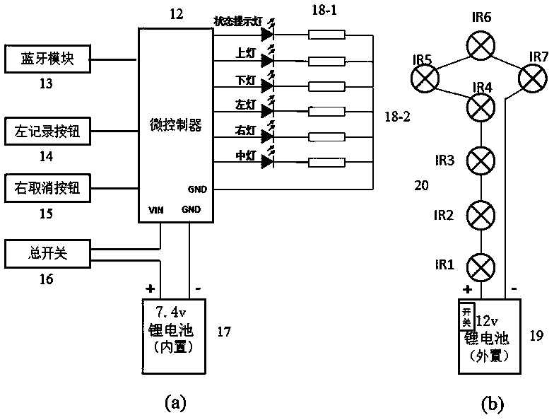
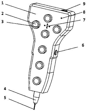
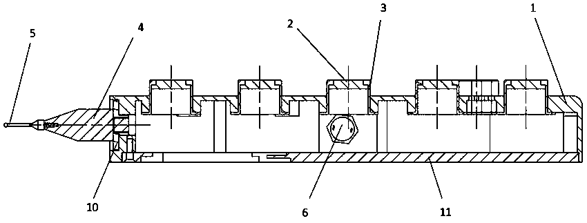
[0018] Real-time example one: see Figure 1~Figure 3 , the mechanical parts of the light pen visual target based on the principle of active light include: housing (1), diffusion plate (2), sleeve (3), extension rod (4), probe (5), connecting plate ( 10), the back cover (11), the circuit part includes: microcontroller (12), status indicator light (18-1), direction indicator light (18-2), Bluetooth module (13), left record button (14) , right cancel button (15), main switch (16), 7.4V lithium battery (17), 850nm infrared light-emitting LED (IR1-IR7) (20) and 12V lithium battery (19). It is characterized in that: the housing (1) is connected to the stylus (5) through the connecting plate (10) to form a measurement unit, and the stylus is touched to the target object by holding the target to complete the measurement of the coordinates of the contact point; the infrared light-emitting LED (IR1-IR7) (20) is connected with 12V lithium battery (19) to form an infrared light-emitting par
Embodiment 2
[0019] Embodiment 2: This implementation example is basically the same as the real-time example 1, and the special features are as follows: the lighting unit composed of the light pen type visual target diffuser plate (2) and the sleeve (3): the sleeve (3) is in the form of a tube Shaped structure, hollow inside, the bottom is connected with the end face of the shell (1) by a flange-like step surface, which is convenient to improve the positioning accuracy; the top of the sleeve (3) is a circular through hole, and the diffuser plate (2) is stepped, embedded The through hole at the top of the sleeve (3) forms a complete end face; the circular diffuser plate (2) is beneficial to improve the luminous quality of infrared LEDs and improve the positioning accuracy of the center of the circular spot collected by visual equipment; at the same time, the diffuser plate (2) and the sleeve (3) The coaxial and coplanar design enables the three-coordinate measuring machine to measure the positi
PUM
 Abstract
Description
Claims
Application Information
 - R&D Engineer
- R&D Manager
- IP Professional
- Industry Leading Data Capabilities
- Powerful AI technology
- Patent DNA Extraction
Browse by: Latest US Patents, China's latest patents, Technical Efficacy Thesaurus, Application Domain, Technology Topic.
© 2024 PatSnap. All rights reserved.Legal|Privacy policy|Modern Slavery Act Transparency Statement|Sitemap