Ultrasonic imaging apparatus and image display method thereof

an ultrasonic imaging and display method technology, applied in the field of ultrasonic imaging apparatus and image display method thereof, can solve the problem of failure to execute ultrasonic diagnosis, and achieve the effect of convenient us

Active Publication Date: 2014-11-13
SAMSUNG ELECTRONICS CO LTD
View PDF0 Cites 0 Cited by
  • Summary
  • Abstract
  • Description
  • Claims
  • Application Information

AI Technical Summary

Benefits of technology

The technical effect of this invention is to create an easy-to-use ultrasound device for medical use with basic measurements without requiring advanced training.

Problems solved by technology

This patent describes different types of ultrasound imaging devices: 1) Ultrasonics Imaging Apparatuses (USI), which uses sound waves to create images on objects like humans; 2) Sonography (SIG), which involves capturing ultrasonic waves caused by reflection off internal parts of the subject's body, allowing users to see them clearly without having to expose themselves to harmful radiation. These techniques help healthcare professionals diagnose diseases more accurately and efficiently.

Method used


Image

  • Ultrasonic imaging apparatus and image display method thereof
  • Ultrasonic imaging apparatus and image display method thereof
  • Ultrasonic imaging apparatus and image display method thereof

Examples


Embodiment Construction

[0039]Reference will now be made in detail to exemplary embodiments, examples of which are illustrated in the accompanying drawings, wherein like reference numerals refer to like elements throughout.

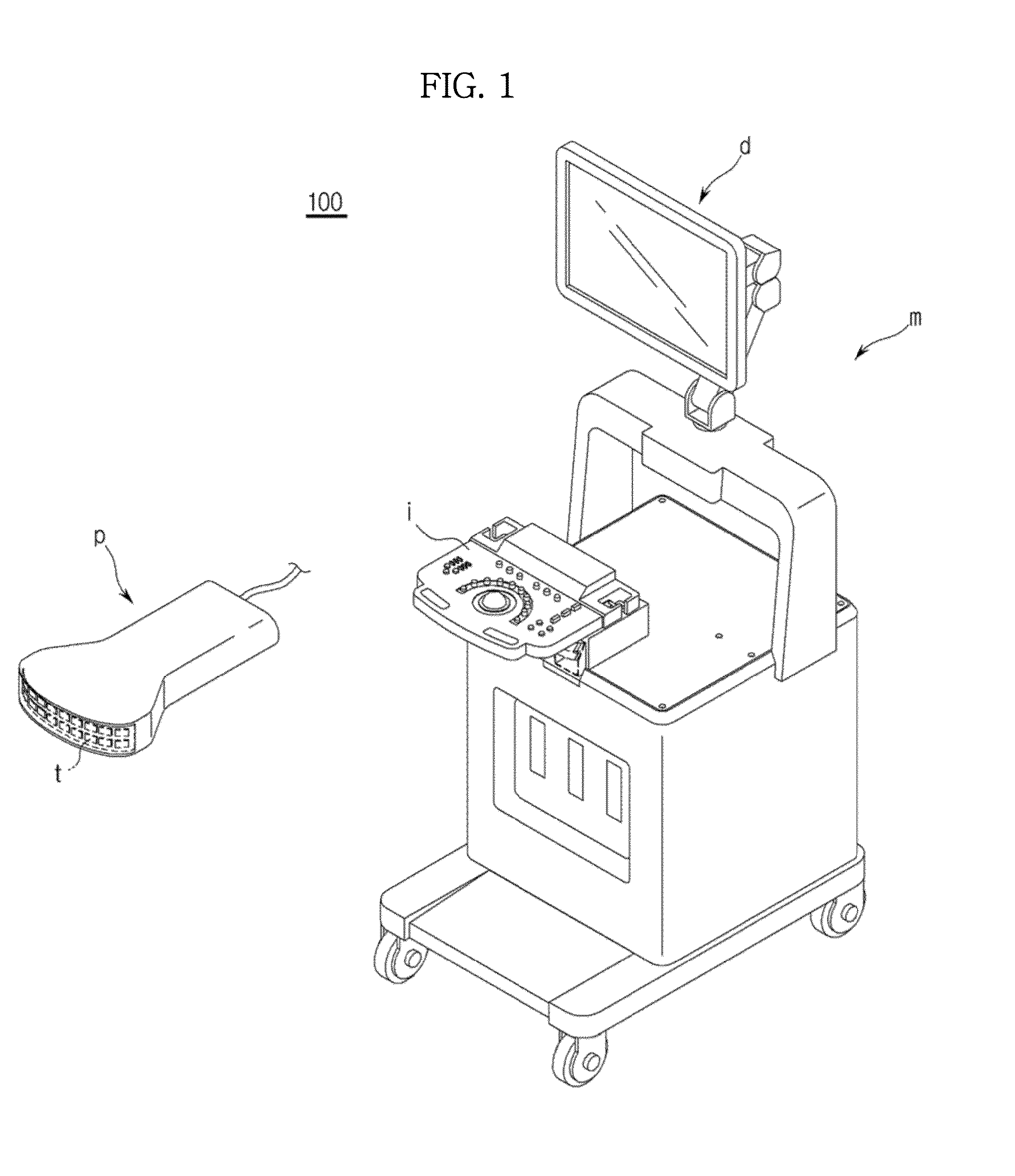
[0040]FIG. 1 is a perspective view which illustrates an external appearance of an ultrasonic imaging apparatus, in accordance with an exemplary embodiment.

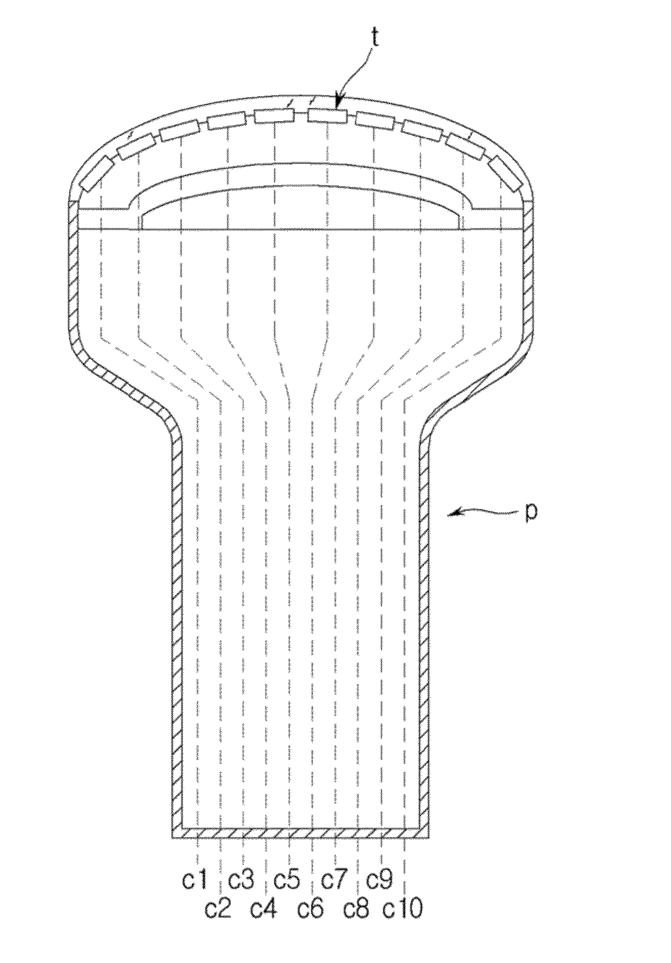
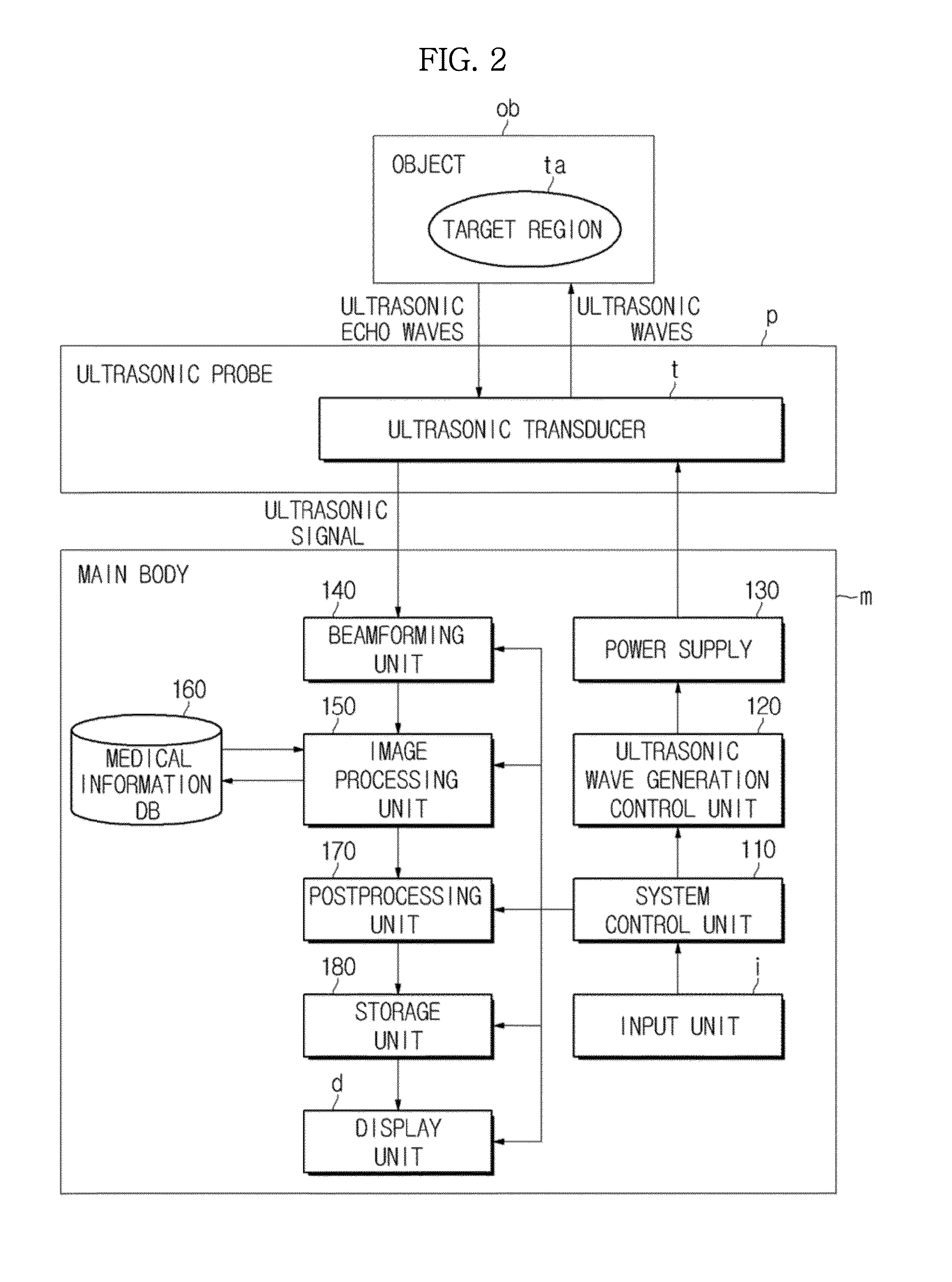
[0041]An ultrasonic imaging apparatus is an imaging apparatus which transmits ultrasonic waves toward a target region within an object, for example, a human body, from the surface of the object, receives ultrasonic waves (i.e., ultrasonic echo waves) reflected by the target region, and generates tomographic images of various tissues or structures within the object by using the received ultrasonic information. As exemplarily shown in FIG. 1, an ultrasonic imaging apparatus 100 may include an ultrasonic probe p which is configured to transmit ultrasonic waves toward an object, to receive ultrasonic echo waves from the object, and to convert


PUM


Abstract

Disclosed herein are an ultrasonic imaging apparatus and an image display method thereof. The ultrasonic imaging apparatus includes an ultrasonic probe configured to transmit ultrasonic signals toward an object and to receive ultrasonic signals reflected by the object, a beamformer configured to perform beamforming based on the ultrasonic signals received by the ultrasonic probe, and an image processor configured to generate an ultrasonic image of an examined region within the object based on the beamforming, to extract characteristic information which relates to the examined region from the generated ultrasonic image, and to judge whether or not the examined region coincides with a target region based on the extracted characteristic information, thus facilitating a determination as to with which region within the object the examined region corresponds based on various pieces of the characteristic information of the examined region extracted via analysis of the ultrasonic image.

Description


Claims


Application Information

Patent Timeline
Owner SAMSUNG ELECTRONICS CO LTD
Why Eureka
Try Eureka