Non-vented vial access syringe

Active Publication Date: 2014-09-18
CAREFUSION 303 INC
View PDF5 Cites 55 Cited by
  • Summary
  • Abstract
  • Description
  • Claims
  • Application Information

AI Technical Summary

Benefits of technology

[0009]In certain embodiments, a pre-filled syringe is disclosed that contains a prefill volume of a medical fluid. The syringe includes a plunger having a plunger tube having proximal and distal ends, a center tube coupled to the proximal end of the plunger tube and extending within the plunger tube toward the distal end, the center tube having a center passage, and a balloon disposed over the center tube and sealingly fixed to at least one of the center tube and the plunger tube. The balloon and the at least one of the center tube and the plunger tube form a gas volume containing a gas. The syringe also includes a barrel having a barrel tube having proximal and distal ends and an interior configured to accept

Problems solved by technology

In the case of a liquid medication, extraction of the liquid without introducing a gas into the vial results in a partial vacuum being created within the vial, which makes the extraction of the liquid more difficult.
In the case of a dry medication,

Method used


Image

  • Non-vented vial access syringe
  • Non-vented vial access syringe
  • Non-vented vial access syringe

Examples


Embodiment Construction

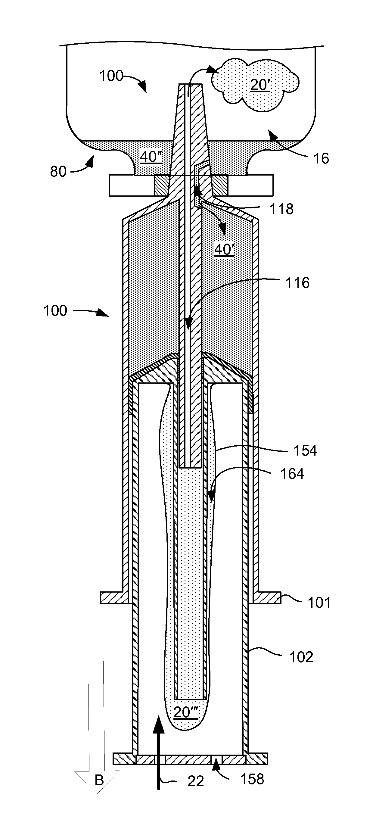
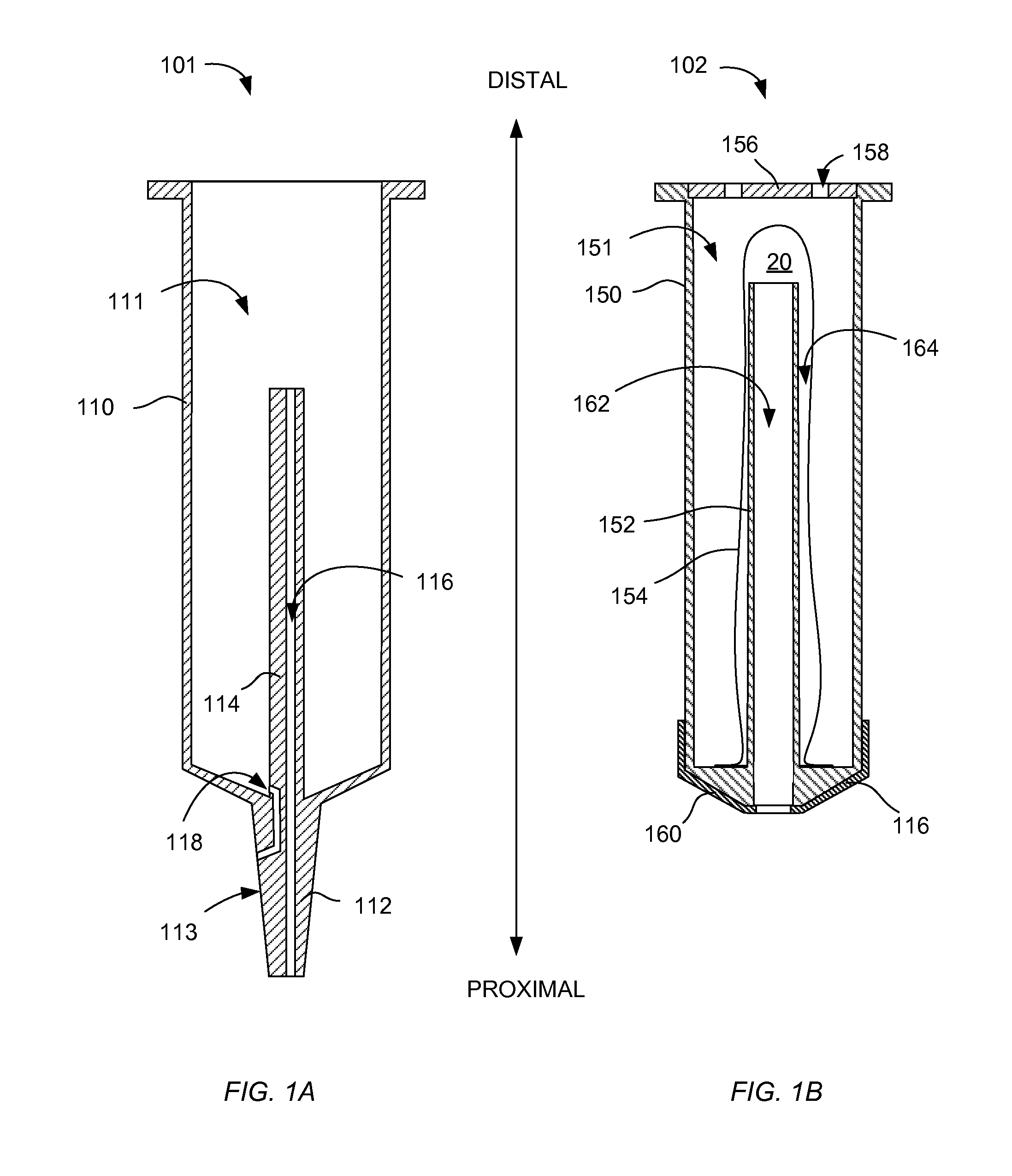
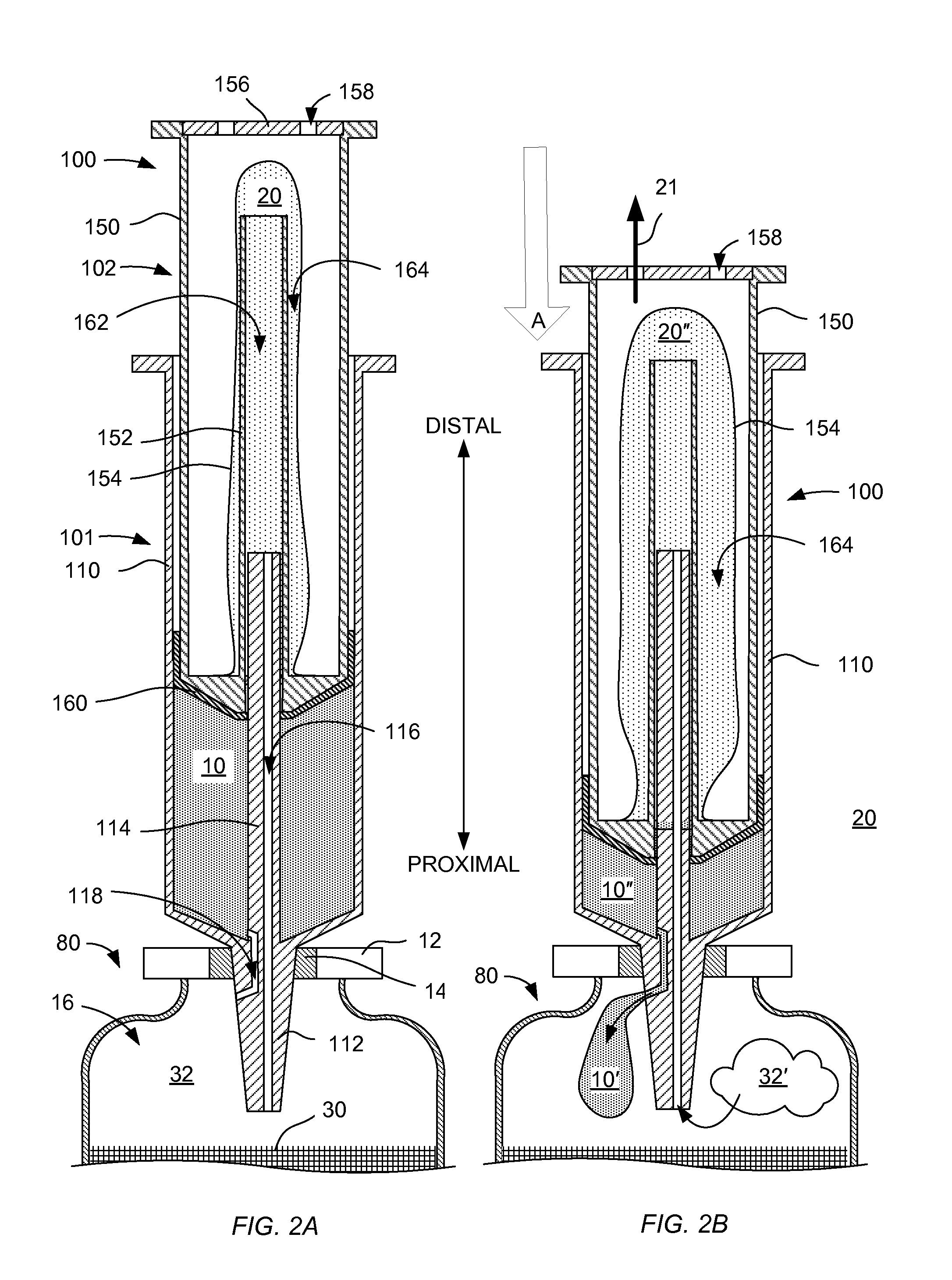
[0016]The syringe disclosed herein is adapted for use with a sealed vial, in various embodiments, so as to maintain a generally constant pressure within the vial while adding or removing liquid. In certain embodiments, the disclosed syringe accepts a flow of gas from the vial that is displaced by liquid being introduced into the vial by the syringe and captures this displaced air, so as to prevent escape of the displaced air and any entrained medication into the ambient atmosphere. In certain embodiments, the disclosed syringe includes a reservoir of sterile air and provides a flow of this sterile air into the vial to replace liquid that is withdrawn from the vial by the syringe. The syringe may be used, in certain embodiments, directly with a vial or, in other embodiments, with a vial adapter configured to extend the liquid and gas passages of the syringe into the vial.

[0017]In the following detailed description, numerous specific details are set forth to provide a full understanding


PUM


Abstract

A syringe includes a plunger having a plunger tube with proximal and distal ends, a center tube with a center passage that extends within the plunger tube, and a balloon disposed over the center tube and sealingly fixed to at least one of the center tube and the plunger tube. The syringe also includes a barrel having a barrel tube having proximal and distal ends and an interior configured to accept a portion of the plunger, a tip fixedly coupled to the proximal end of the barrel tube, a post fixedly attached to the tip and extending within the barrel tube toward the distal end, the tip configured to partially extend into the center passage of the plunger, and a gas passage extending from a proximal end of the tip to the distal end of the post.

Description


Claims


Application Information

Patent Timeline
Owner CAREFUSION 303 INC
Why Eureka
Try Eureka