Smart injector

a smart injector and injector technology, applied in the field of smart injectors, can solve the problems of inability to provide meaningful, accurate information regarding the progress of injection, requiring relatively slow, and requiring measurement administration that may take up to approximately an hour to complete,

Active Publication Date: 2020-02-13
BIOGEN MA INC
View PDF0 Cites 0 Cited by
  • Summary
  • Abstract
  • Description
  • Claims
  • Application Information

AI Technical Summary

Benefits of technology

The invention provides an improved device for controlling or measuring how much fluid needs being used by a larger volume injectors over time. This helps prevent issues such as excessive use caused by too many fluids needed at once.

Problems solved by technology

The technical problem addressed in this patents relates to improving conventional small volume injectors with advanced functions like monitoring medicine displacement (involved in delivering precise quantities), wirelessly communicating with external equipment, controlling injection rates, etc., without requiring excessively long periods between each treatment cycle due to insolubility issues associated with drugs used today. Additionally, existing mechanisms have limitations in terms of adjustment speed, accuracy, reliance upon electronic components, durability, and ease of use.

Method used


Image

  • Smart injector
  • Smart injector
  • Smart injector

Examples


Embodiment Construction

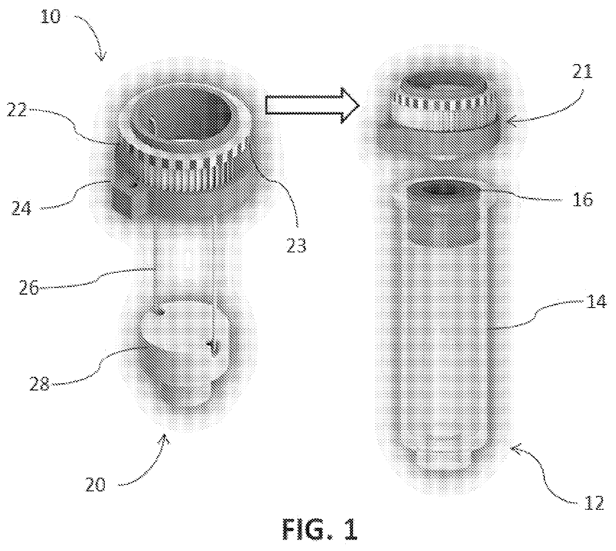
[0016]The claimed subject matter is described with reference to the drawings, wherein like reference numerals are used to refer to like elements throughout. In the following description, for purposes of explanation, numerous specific details are set forth in order to provide a thorough understanding of the subject innovation. It may be evident, however, that the claimed subject matter may be practiced without these specific details. In other instances, well-known structures and devices are shown in block diagram form in order to facilitate describing the subject innovation. Moreover, it is to be appreciated that the drawings may not be to scale. Moreover, the words “exemplary” or “illustrative” are used herein to mean serving as an example, instance, or illustration. Any aspect or design described herein as “exemplary” or “illustrative” is not necessarily to be construed as preferred or advantageous over other aspects or designs.

[0017]According to an illustrative embodiment of the disc


PUM


Abstract

A device that regulates, monitors, and provides data on the progress of a large-volume injector during its injection sequence. The device comprises an injector and a monitor assembly. The injector has a syringe having a plunger, and a biasing device that biases the plunger through the syringe. The monitor assembly comprises a resistance unit configured to resist movement of the plunger, a gear connected to the plunger by the resistance unit, and a control unit configured to monitor the position, and regulate the rotation, of the gear. Wherein linear movement of the plunger causes the gear to rotate so that the control unit generates information on the position of the plunger.

Description


Claims


Application Information

Patent Timeline
Owner BIOGEN MA INC
Why Eureka
Try Eureka