Device and system for ultrasonic inspection

a technology of ultrasonic inspection and probe devices, applied in the field of ultrasonic inspection, can solve the problems of limiting the size and/or scope of the actuating mechanism of the system, limiting the proper cabling and/or peripheral devices, and limiting the use of actuating mechanisms. the effect of signal communication

Active Publication Date: 2014-12-04
BAKER HUGHES INC
View PDF8 Cites 8 Cited by
  • Summary
  • Abstract
  • Description
  • Claims
  • Application Information

AI Technical Summary

Benefits of technology

In this patented technology, there are improvements made on an improved way to inspect objects without damaging them or causing damage during their manufacturing process. These modifications include adding electronic components into probing assembly design to create waveforms and detect any defects caused by cracks formed within it. Additionally, they have supporting structures with signal processing capabilities like phase arrays to communicate relevant data about the detected problem being addressed.

Problems solved by technology

Technologies described by this patents involve creating probes called "walls," which cover tiny parts within objects like pipe walls while still being able to transmit sound waves when excited through electricity pulse excitation techniques. However, these technical problem addressed in previous researchers has been how to efficiently inspect large areas without having to manually adjust their placement due to limited spaces near them.

Method used


Image

  • Device and system for ultrasonic inspection
  • Device and system for ultrasonic inspection
  • Device and system for ultrasonic inspection

Examples


Embodiment Construction

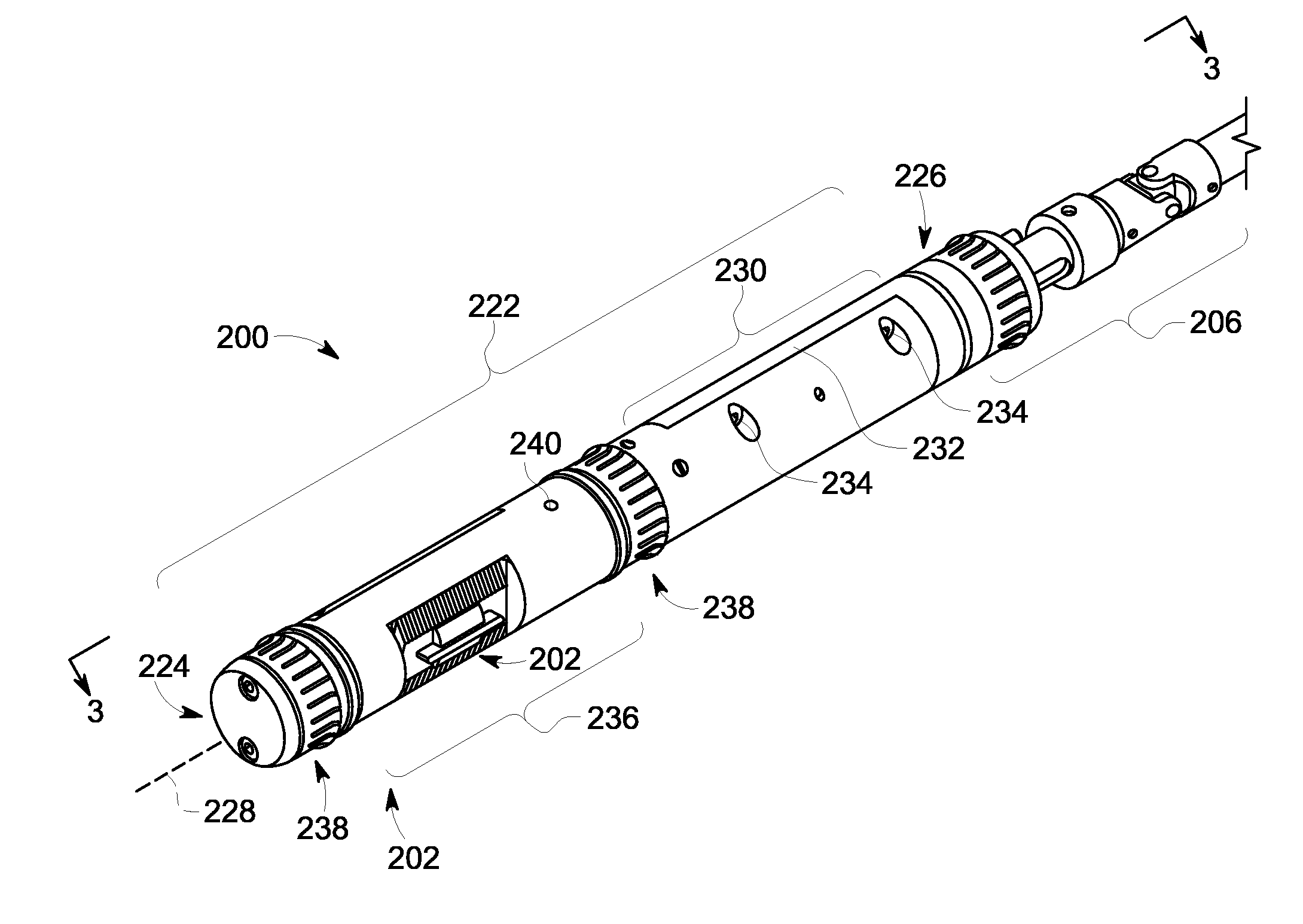
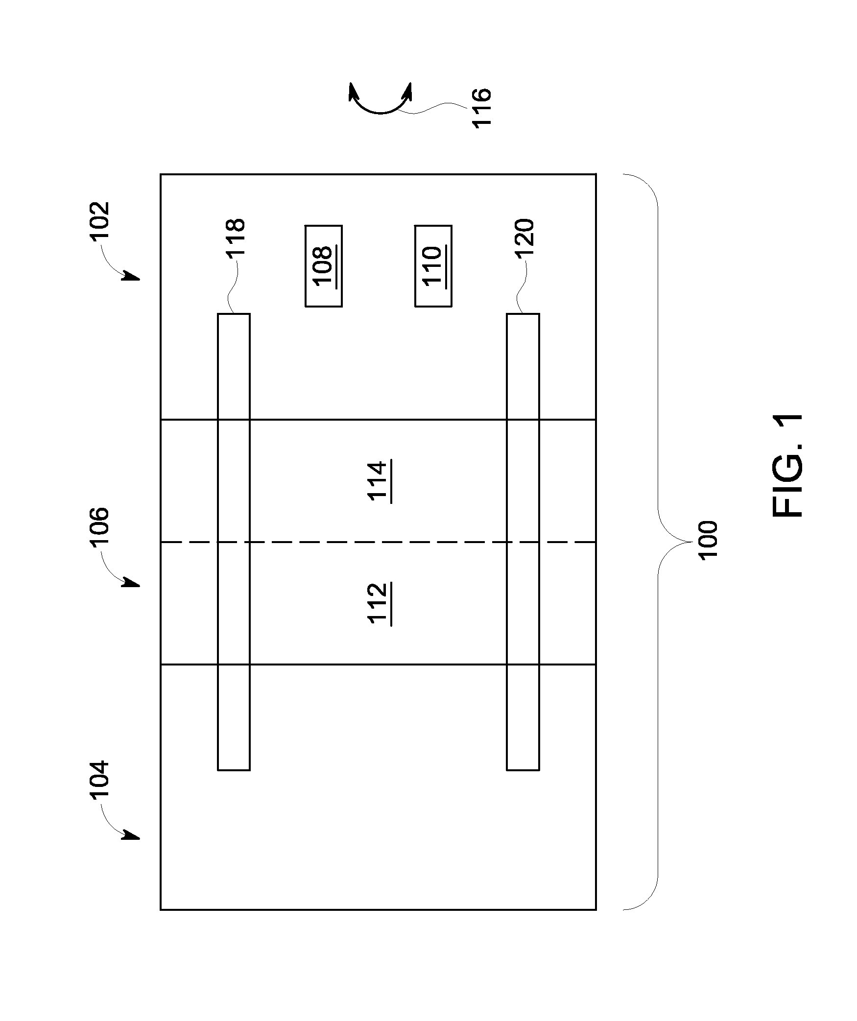
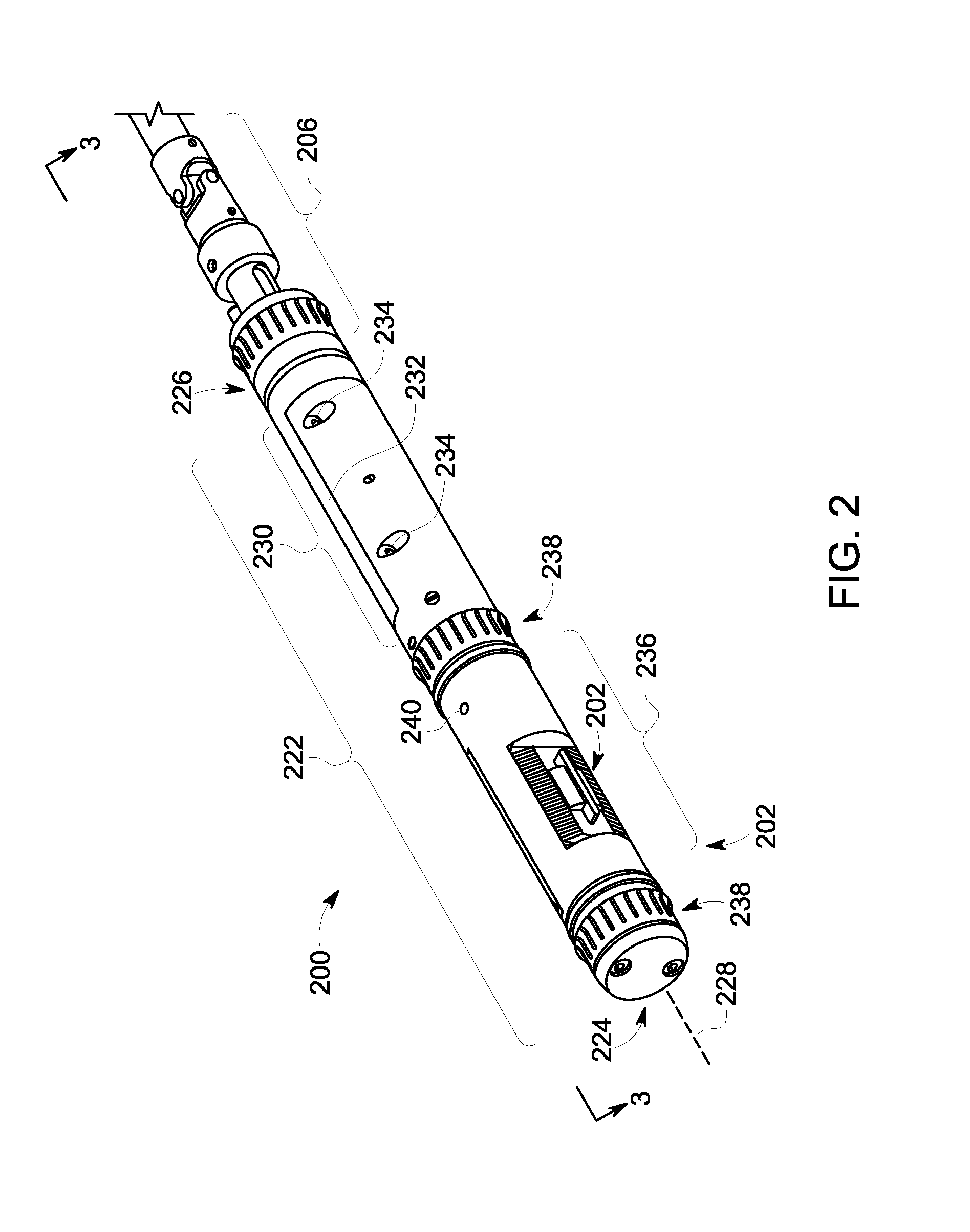
[0023]FIG. 1 illustrates a schematic diagram of an exemplary embodiment of a probe assembly 100 that can generate ultrasonic signals for use in non-destructive inspection. The probe assembly 100 includes a probe component 102, an interface component 104, and a rotary component 106, which couples the probe device 102 to the interface component 104. The probe component 102 includes one or more probe elements (e.g., a first probe element 108) and a probe control component 110 that can exchange signals (e.g., electrical signals) with the first probe element 108. The rotary component 106 has a stationary part 112 and a rotating part 114. Examples of the parts 112, 114 can actively rotate the probe device 100, as generally indicated by the enumerated arrow 116. The probe assembly 100 also has one or more operating components (e.g., a fluid component 118 and a signal component 120). The operating components 118, 120 conduct inputs and outputs (e.g., fluids, electrical signals, etc.) between t


PUM


Abstract

This disclosure describes embodiments of a probe assembly and an inspection system for ultrasonic inspection. Designs for the probe assembly package components to fit into a bore of a hollow target. These designs may incorporate electronics to generate waves and to detect a wide selection of anomalies (e.g., transversal crack, longitudinal crack, and volumetric flaws) that can form in the hollow target. The probe assembly provides support structure to manipulate and operate these electronics in the bore. This support structure facilitates communication of signals, e.g., from transducer elements that operate as a phased array. The probe assembly also includes a fluid circulating system and coupling system that permits the probe device to detach and reattach to match the probe device (and other parts of the probe assembly) to the size of the bore. These systems allow for fluid and electrical signals to circulate through the probe assembly.

Description


Claims


Application Information

Patent Timeline
Owner BAKER HUGHES INC
Why Eureka
Try Eureka