Bio-sensing device

a biosensor and sensor technology, applied in the field of biosensors, can solve the problems of low bacterial disinfectant efficacy, high cost, and high cost of frequent application of flow cytometry, and achieve the effect of effective function

Active Publication Date: 2015-01-08
WISTRON CORP
View PDF9 Cites 1 Cited by
  • Summary
  • Abstract
  • Description
  • Claims
  • Application Information

AI Technical Summary

Benefits of technology

In this new design for separating cells from blood plasma or other liquids containing small particles suspended therein by controlling their movement through electromagnetic fields without affecting them' characteristics such as size or shape. This allows these tiny objects like bacteria to move freely throughout the liquid while being separated into different parts during processing.

Problems solved by technology

The technical problem addressed in this patents relates to improving the efficiency at collecting small amounts of biological material while maintaining high levels of sterility during processing or analysis processes due to their use of expensive equipment like flowcytometer and microscope separators.

Method used


Image

  • Bio-sensing device
  • Bio-sensing device
  • Bio-sensing device

Examples


Embodiment Construction

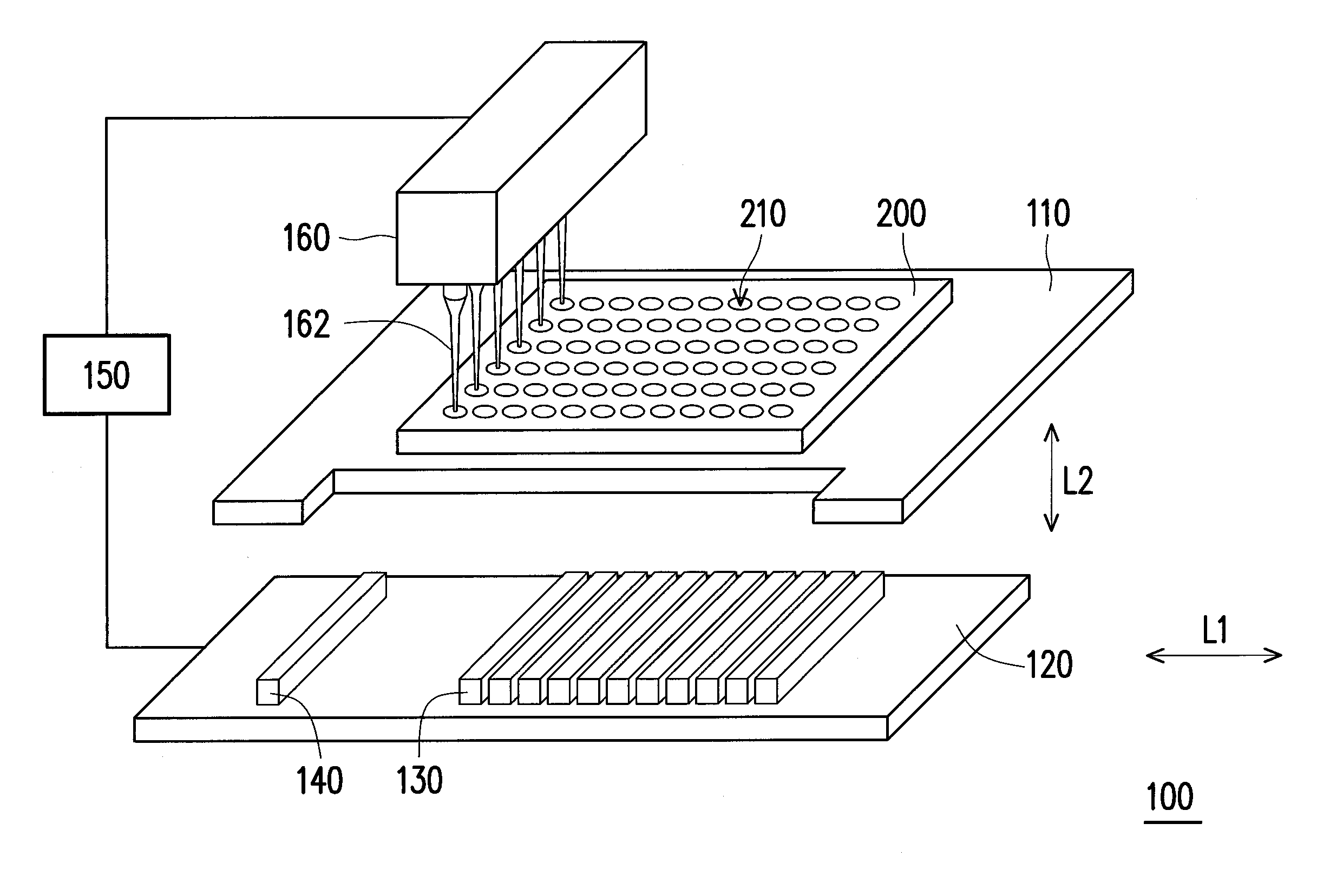
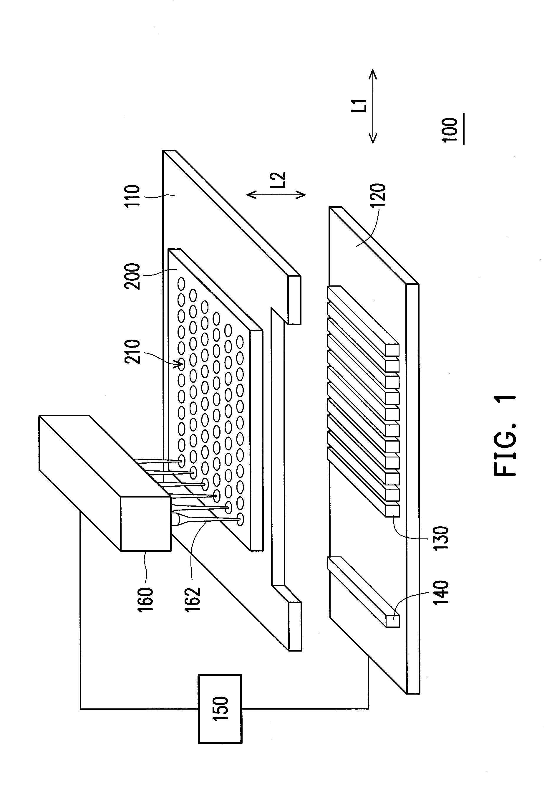
[0028]FIG. 1 is a schematic view illustrating a bio-sensing device according to an embodiment of the invention. FIG. 2 is a partial side view illustrating the bio-sensing device depicted in FIG. 1. FIG. 3 is a partial enlarged view of FIG. 2. With reference to FIG. 1 to FIG. 3, in the present embodiment, the bio-sensing device 100 includes a first platform 110, a second platform 120, at least one first magnetic element 130, at least one second magnetic element 140, a control device 150, and an injection device 160. The first platform 110 is configured to support a microplate 200, the microplate 200 has a plurality of wells 210, and each of the wells 210 stores a reagent 300 and a plurality of microbeads 400 (shown in FIG. 3), so as to perform the separation processes.

[0029]In the present embodiment, the second platform 120 is located below the first platform 110, the first magnetic elements 130 are arranged in arrays on the second platform 120 along an axis L1, and the second magnetic


PUM


Abstract

A bio-sensing device includes a first platform, a second platform, at least one first magnetic element, and at least one second magnetic element. The first platform is configured to support a microplate. The microplate has a plurality of wells, each of which stores a reagent and a plurality of microbeads. The second platform is movably placed below the first platform. The first and the second magnetic elements are respectively located on the second platform. The first magnetic element moves along with the second platform to magnetically attract the microbeads in the wells, the second magnetic element moves along with the second platform to demagnetize the microbeads in the wells, and magnetism of the first magnetic element is opposite to magnetism of the second magnetic element.

Description


Claims


Application Information

Patent Timeline
Owner WISTRON CORP
Why Eureka
Try Eureka