Flip-lock type electrical device

Inactive Publication Date: 2015-07-16
QUANTA COMPUTER INC
View PDF2 Cites 13 Cited by
  • Summary
  • Abstract
  • Description
  • Claims
  • Application Information

AI Technical Summary

Problems solved by technology

However, if the antennas are manufactured by Laser Direct Str

Method used


Image

  • Flip-lock type electrical device
  • Flip-lock type electrical device
  • Flip-lock type electrical device

Examples


Embodiment Construction

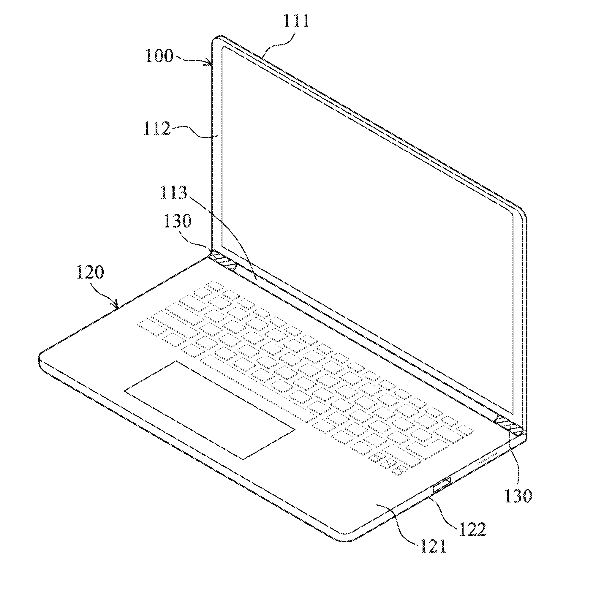
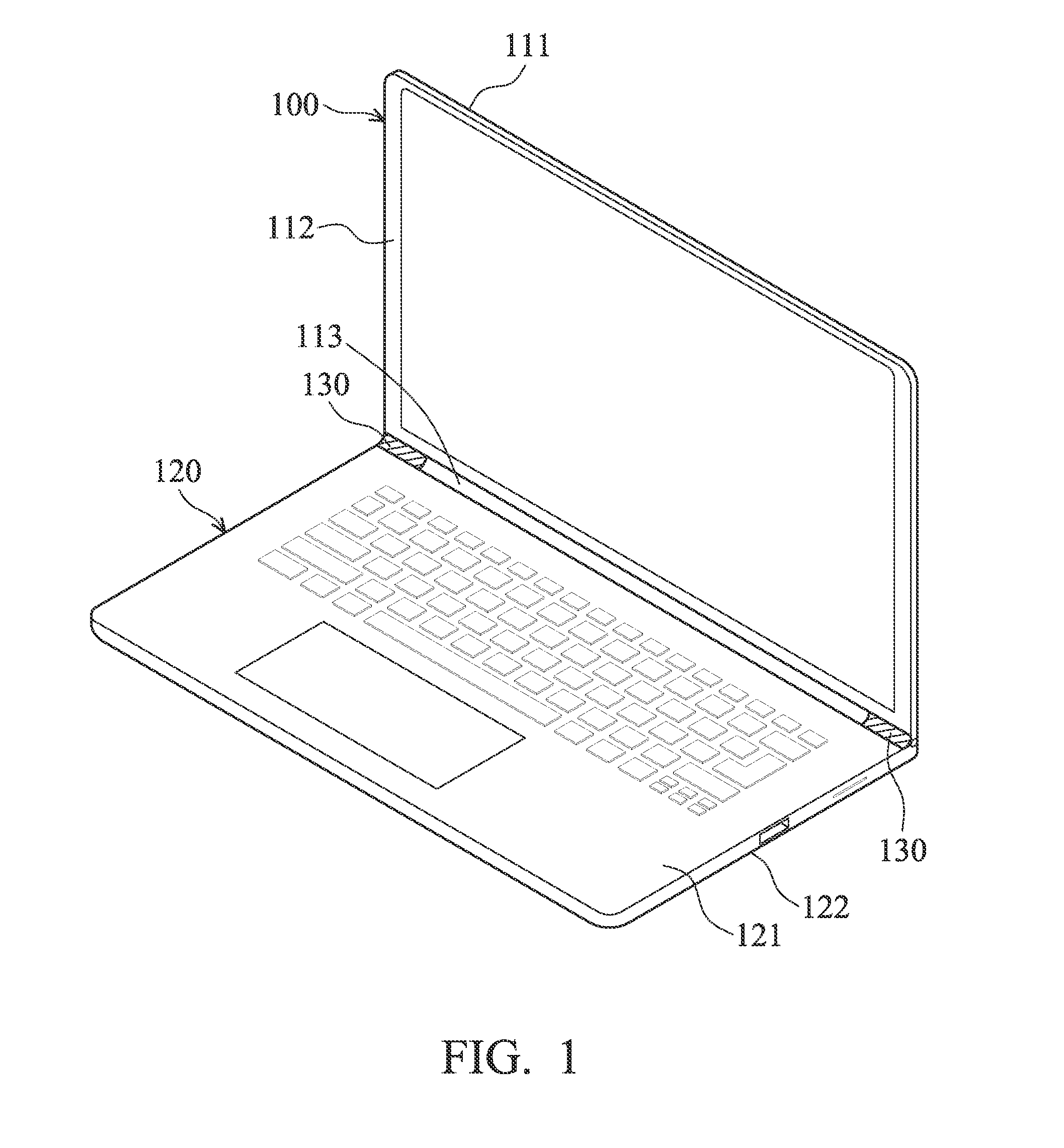
[0013]FIG. 1 is schematic diagram illustrating the flip-lock type electrical device 100 according to an embodiment of the invention. As shown in FIG. 1, the flip-lock type electrical device 100 comprises a lid part 110, a main part 120 and a hinge part 130. The flip-lock type electrical device 100 may be a notebook, a smartphone, or a personal digital assistant (PDA), etc., but it is to be understood that the invention is not limited thereto. Those who are skilled in this technology can apply the flip-lock type electrical device 100 in computer-system configurations such as hand-held devices, portable devices, microprocessor-based or programmable consumer electronics and other similar devices. Note that the flip-lock type electrical device 100 in the embodiments of the invention is regarded as a notebook, and it is to be understood that the invention is not limited thereto.

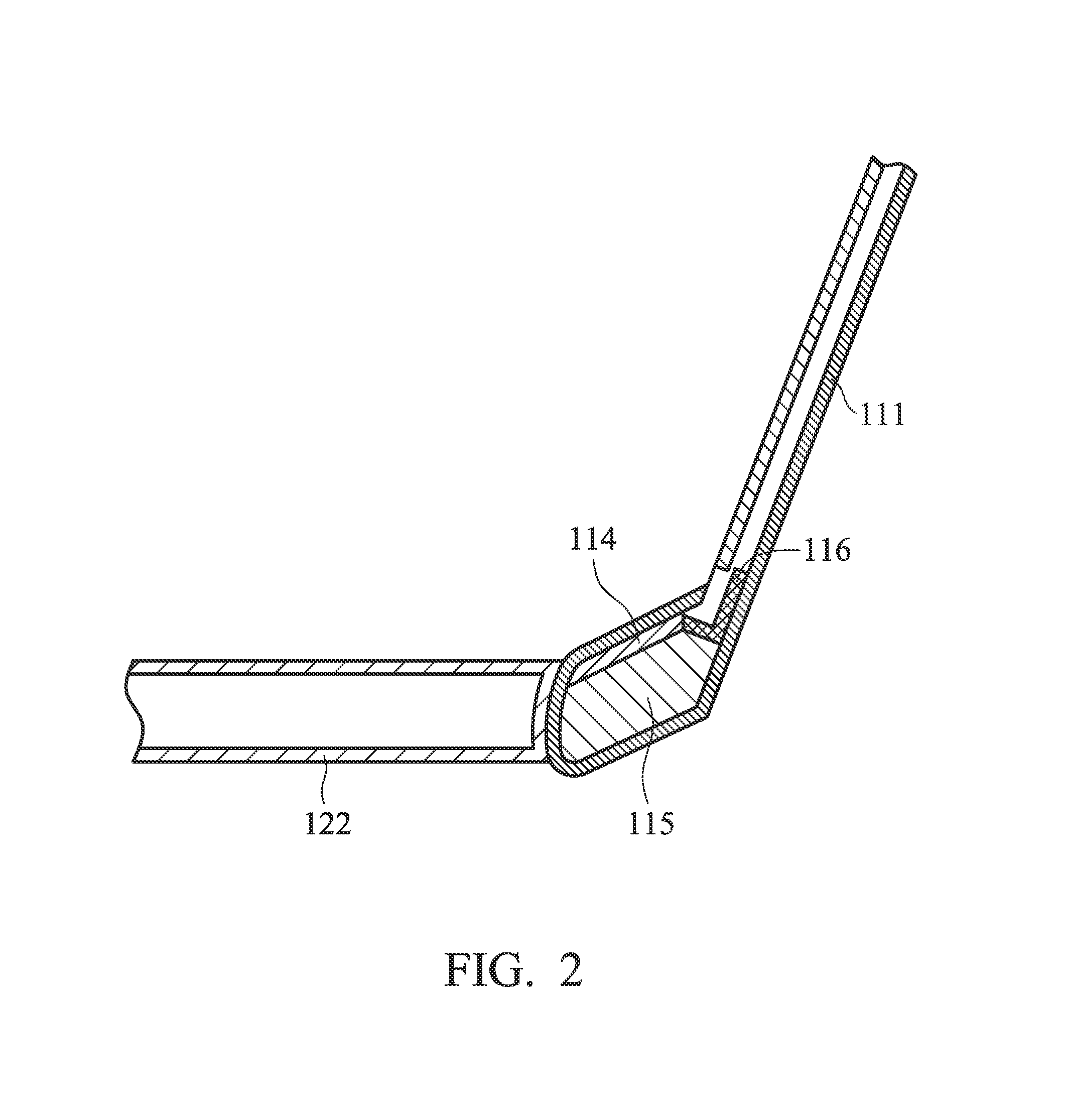
[0014]In an embodiment of the invention, the lid part 110 includes a metal part 111 and a non-metal part 112. The


PUM


Abstract

A flip-lock type electrical device is provided. The flip-lock type electrical device includes a lid part which includes a metal part and a non-metal part, wherein the metal part includes a hinge cap, and one or a plurality of antennas, and one or a plurality of non-metal support material are configured in the hinge cape, and the hinge cape includes an antenna window, and wherein the antenna is grounded to the metal part, a main part, which includes a keyboard part and a base part, and a hinge part, configured to connect the lid part with the main part.

Description


Claims


Application Information

Patent Timeline
Owner QUANTA COMPUTER INC
Why Eureka
Try Eureka