Long-stroke high-precision piezoelectric displacement platform and driving method thereof
A high-precision, electric displacement technology, applied to the parts of the instrument, the instrument, the shell, etc., can solve the problems of weak bearing capacity, limited stroke, unstable movement, etc., to achieve increased force bearing area, uniform force, Effect of improving mechanical output characteristics
- Summary
- Abstract
- Description
- Claims
- Application Information
AI Technical Summary
Benefits of technology
Problems solved by technology
Method used
Image

Examples
specific Embodiment approach 1
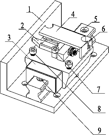
[0039] Specific implementation mode one: combine Figure 1~Figure 9 This embodiment will be described. This implementation mode provides a specific implementation scheme of a long-stroke high-precision piezoelectric displacement stage. The long-stroke high-precision piezoelectric displacement stage consists of a fixed base 1, a driving stator 2, a bearing slider 3, a top cover 4, a guide rail 5, a thread pair 6, stator mounting screws 7, top cover mounting screws 8 and guide rail mounting screws 9 composition.
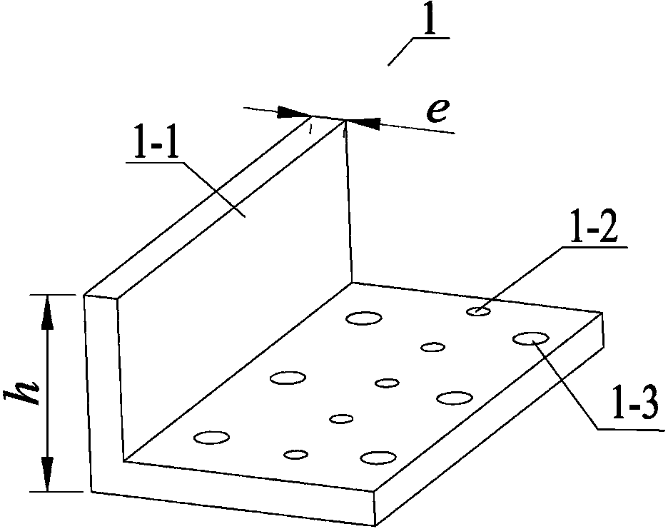
[0040] The fixed base 1 adopts an "L"-shaped structure, and the fixed base 1 includes a friction plane 1-1, a guide rail threaded mounting hole 1-2 and a fixed base mounting hole 1-3; the end surface of the friction plane 1-1 is coated with For ceramic and glass fiber friction materials, the friction plane 1-1 has a thickness of e , with a height of h made of stainless steel, h The ratio to e is S= h / e , where the value of S should be less than 20; the guide r
specific Embodiment approach 2
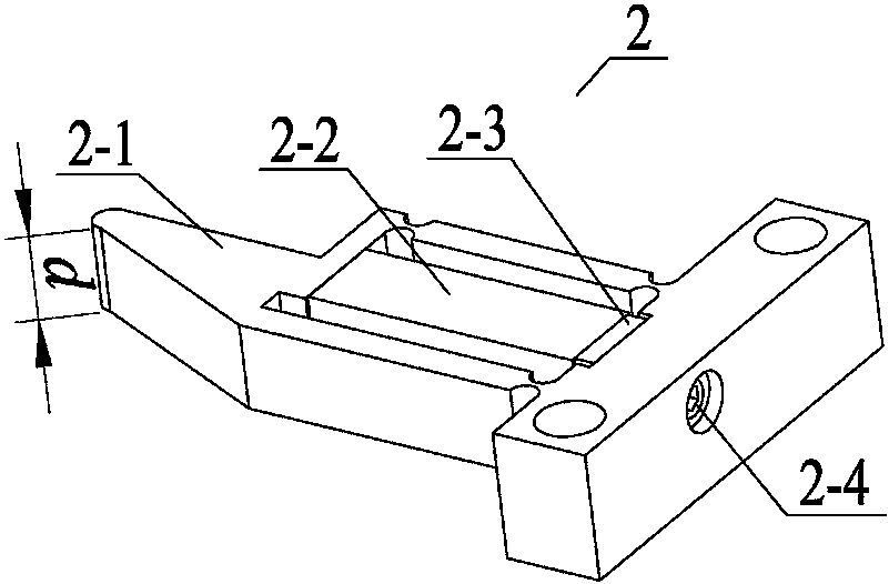
[0046] Specific implementation mode two: combination Figure 10~Figure 11 This embodiment will be described. This embodiment provides a long-stroke and high-precision piezoelectric displacement stage realized by a double-stack single-drive foot stator assembly. Its structural composition and connection method are the same as those in the first embodiment, except that the specific structure of the flexible hinge mechanism 2-1 in the driving stator 2 is different.
[0047] The stacked piezoelectric ceramic 2-2 is fixed in the flexible hinge mechanism 2-1 through the adjusting gasket 2-3 and the Kimi screw 2-4; the flexible hinge mechanism 2-1 is provided with a driving foot 2-1 -1, beam 2-1-2, stator mounting hole 2-1-4, Kimi screw mounting hole 2-1-6, rigid straight beam 2-1-8, straight circular hinge Ⅰ 2-1-9, Rigid beam 2-1-10, straight round hinge Ⅱ 2-1-13, straight round hinge Ⅲ 2-1-14, straight round hinge Ⅳ 2-1-15, straight round hinge Ⅴ 2-1- 16 and straight circular hinge
specific Embodiment approach 3
[0048] Specific implementation mode three: combination Figure 12~Figure 13 This embodiment will be described. This embodiment provides a long-stroke high-precision piezoelectric translation stage realized by a double-stack arched stator assembly. Its structural composition and connection method are the same as those in the first embodiment, except that the specific structure of the flexible hinge mechanism 2-1 in the driving stator 2 is different.
[0049] The flexible hinge mechanism 2-1 is provided with a driving foot 2-1-1, a beam 2-1-2, a stator mounting hole 2-1-4, a base screw mounting hole 2-1-6, and an oval hinge II 2 -1-5, elliptical hinge Ⅰ 2-1-11, rigid beam Ⅱ 2-1-20, rigid curved beam Ⅰ 2-1-60, rigid curved beam Ⅱ 2-1-61, rigid curved beam Ⅲ 2- 1-62 and Rigid Curved Beam IV 2-1-63. The driving foot 2-1-1 is located in the middle of the beam 2-1-2, the end of the driving foot 2-1-1 is coated with friction material, and the driving foot 2-1-1 is in line with the fri
PUM
 Abstract
Description
Claims
Application Information
 - R&D Engineer
- R&D Manager
- IP Professional
- Industry Leading Data Capabilities
- Powerful AI technology
- Patent DNA Extraction
Browse by: Latest US Patents, China's latest patents, Technical Efficacy Thesaurus, Application Domain, Technology Topic.
© 2024 PatSnap. All rights reserved.Legal|Privacy policy|Modern Slavery Act Transparency Statement|Sitemap