Supple crawling actuating mechanism

An actuating mechanism and compliant technology, applied in the directions of generator/motor, piezoelectric effect/electrostrictive or magnetostrictive motor, electrical components, etc. Compactness and other issues to achieve the effect of simple structure, fast response and easy processing

Inactive Publication Date: 2019-05-03
NANJING UNIV OF AERONAUTICS & ASTRONAUTICS
View PDF5 Cites 4 Cited by
  • Summary
  • Abstract
  • Description
  • Claims
  • Application Information

AI Technical Summary

Problems solved by technology

[0005] However, the current piezoelectric inchworm linear motors still have the following deficiencies: 1. Large volume and uncompact structure
2. Low motor stability
3. The motor cannot be clamped with power off
4. It can only move in a straight line, but not in a curved line

Method used


Image

  • Supple crawling actuating mechanism
  • Supple crawling actuating mechanism
  • Supple crawling actuating mechanism

Examples


Embodiment 1

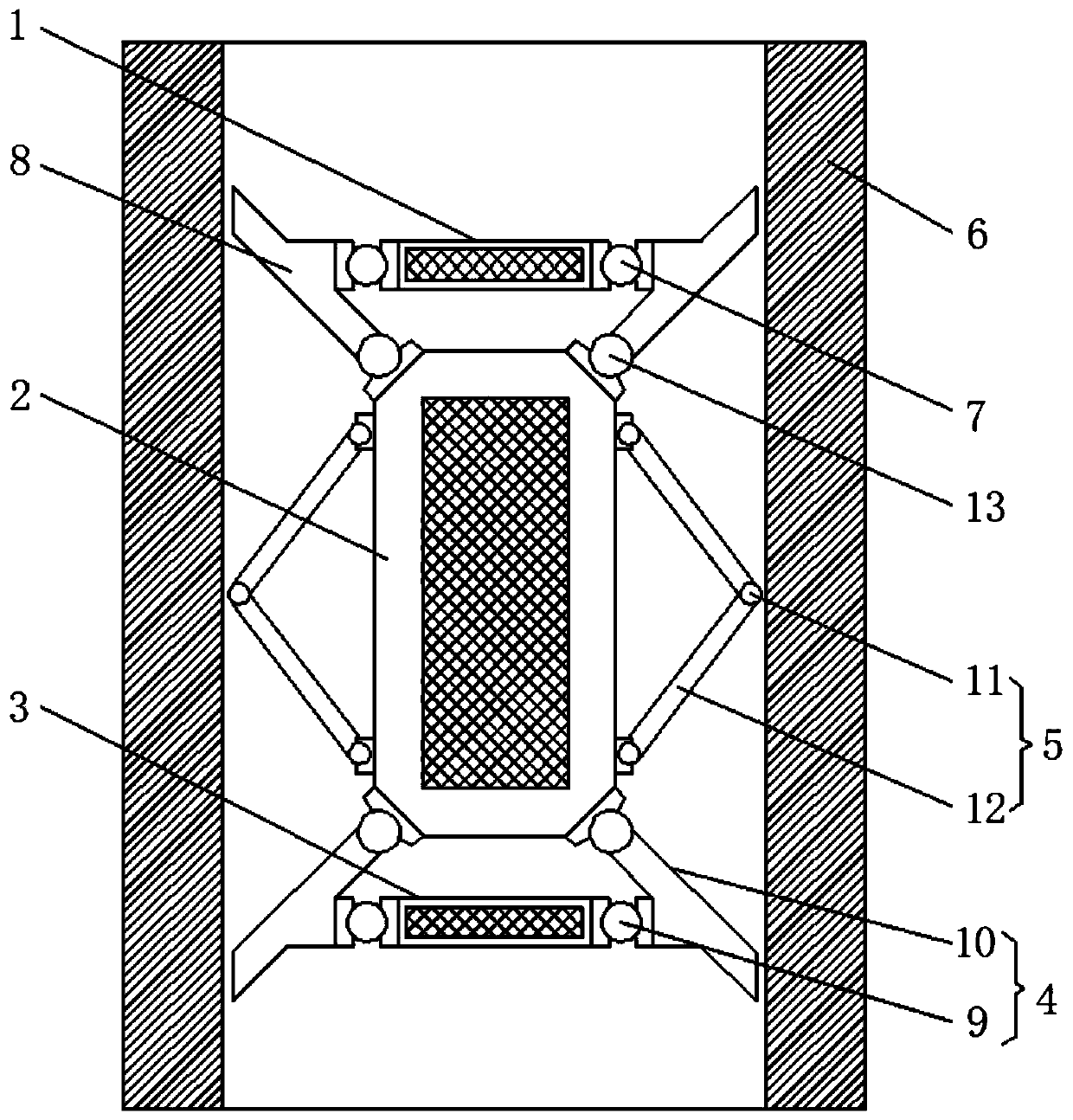
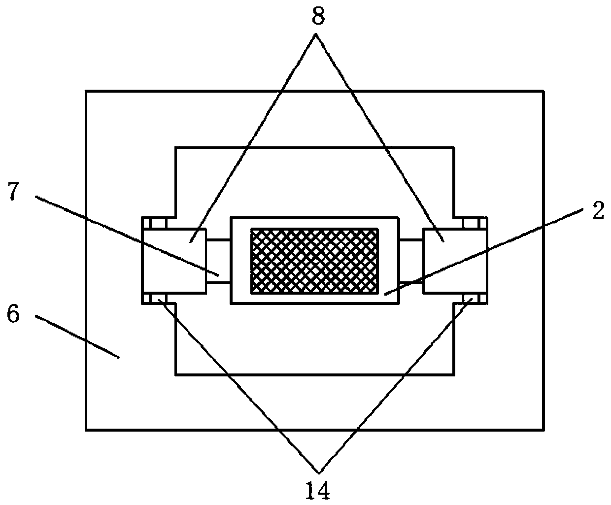
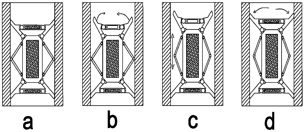
[0045] When the present invention is powered on, the front clamping mechanism 1 and the rear clamping mechanism 3 are elongated by external excitation, and the front clamping claw 8 and the rear clamping claw 10 are clamped in the rigid guide rail 6, so that the crawling actuating mechanism is fixed on the rigid rail. Inside the guide rail 6, then reduce the voltage of the external excitation front clamping mechanism 1, the front clamping mechanism 1 shrinks, the front clamping claw 8 is separated from the rigid guide rail 6, and at the same time, the external excitation moves the telescopic mechanism 2, and the middle movement telescopic mechanism 2 stretches , the power-off clamping mechanism 5 breaks away from the rigid guide rail 6, and pushes the front clamping mechanism 1 to move forward. After the movement is completed, the voltage of the front clamping mechanism 1 is externally stimulated, the front clamping mechanism 1 is extended, and the front clamping claw 8 is engag...

Embodiment 2

[0047] When the present invention is powered on, the telescopic mechanism 2 is elongated, and the opening angle of the two transmission rods 12 becomes larger, so that the power-off clamping mechanism 5 is separated from the rigid guide rail 6, and the excitation voltage input during work is sometimes high and sometimes low, but It will not be lower than a certain amplitude, and the motion telescopic mechanism 2 expands and contracts with the excitation voltage, but it is always longer than the motion telescopic mechanism 2 in the initial state, so that the power-off clamping mechanism 5 will not be clamped on the rigid guide rail 6 wall, and the whole is compliant The crawling actuation mechanism can run smoothly. When the power is cut off, the motion telescopic mechanism 2 is in the initial state, and the power-off clamping mechanism 5 is clamped on the rigid guide rail 4 .


PUM


Abstract

The invention discloses a supple crawling actuating mechanism. The mechanism includes a front clamping mechanism, a motion telescoping mechanism, a rear clamping mechanism, a displacement amplifying mechanism, a power-off clamping mechanism, and a rigid guide rail; the front clamping mechanism, the motion telescoping mechanism and the rear clamping mechanism have a same structural form; the frontclamping mechanism and the rear clamping mechanism are symmetrically distributed on upper and lower sides of the motion telescoping mechanism; the front clamping mechanism, the motion telescoping mechanism and the rear clamping mechanism are located in the rigid guide rail; the displacement amplifying mechanisms comprises hinges I, front clamping jaws and hinges II, and rear clamping jaws; the front clamping mechanism is connected to the front clamping jaw through the hinges I; the rear clamping mechanism is connected to the rear clamping jaw through the hinges II; and the power-off clamping mechanism includes hinges III and transmission rods, and the transmission rods are symmetrically disposed on both ends of the motion telescoping mechanism the same side. Through unique design construction, the mechanism has the advantages of fast response speed, convenient usage, and immunity from electromagnetic interference, and also has the characteristics of being large in stroke and being capable of moving along a curve.

Description

technical field [0001] The invention relates to the technical field of micro / nano positioning, in particular to a compliant crawling actuation mechanism. Background technique [0002] With the development of micro / nano technology, research in many engineering technology fields urgently needs sub-micron and micro / nano-level precision positioning, and the driver required for a large-stroke, high-resolution precision positioning system must also have a large stroke , high resolution. However, because the traditional electromagnetic motor needs a deceleration device, it is difficult to make a breakthrough in the development direction of miniaturization and high precision, and cannot meet the needs of modern precision machinery. With the development of material science, novel smart materials have proposed new solutions for these applications. [0003] Smart materials have been widely studied and applied in the manufacture of non-electromagnetic actuators due to their sensitive ...

Claims


Application Information

Patent Timeline
IPC IPC(8): H02N2/02
Inventor 杨德华刘赟哲吴常铖费飞
Owner NANJING UNIV OF AERONAUTICS & ASTRONAUTICS
Why Eureka
Try Eureka