Preparation method and application of carbon monoxide near-infrared fluorescent probe
A fluorescent probe and carbon monoxide technology, applied in the field of fluorescent probes, can solve the problems of short emission wavelength and small Stokes shift of fluorescent probes, and achieve good spectral response performance and rapid response
- Summary
- Abstract
- Description
- Claims
- Application Information
AI Technical Summary
Problems solved by technology
Method used
Image


Examples
Example Embodiment
[0025] Example 1:
[0026] Synthesis of fluorescent probe
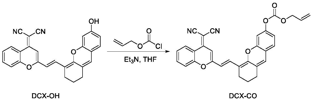
[0027] Synthetic route such as figure 1 . In N 2 Under protection, in a 25 mL round bottom flask, dissolve DCX-OH (209 mg, 0.5 mmol), allyl chloroformate (240 mg, 2.0 mmol), and triethylamine (200 mg, 2.0 mmol) in 10 mL of THF, and then The reaction was stirred overnight at room temperature. After the reaction was completed, diluted with water and used CH 2 Cl 2 Extraction, the resulting organic layer was washed with brine, and then with anhydrous Na 2 SO 4 Dry, filter and concentrate. The crude product is purified by silica gel column chromatography (CH 2 Cl 2 ) To obtain the dark solid product DCX-CO (150 mg, yield 60%), which is the fluorescent probe. 1 H NMR(400MHz, CDCl 3 )δ8.91(d,J=9.3Hz,1H), 8.07(d,J=15.6Hz,1H), 7.73(t,J=7.8Hz,1H), 7.61(d,J=7.6Hz,1H) ,7.43(t,J=7.6Hz,1H), 7.10(d,J=8.3Hz,1H), 7.02(s,1H), 6.88(dd,J=8.3,2.2Hz,1H), 6.77(s, 1H), 6.49 (s, 1H), 6.14 (d, J = 15.5 Hz, 1H), 6.08-6.00 (m, 1H), 5.48 (d, J = 17.1
Example Embodiment
[0028] Example 2:
[0029] Fluorescence probe and CO solution preparation
[0030] Preparation of probe solution: Weigh a certain amount of probe and dissolve it in dimethyl sulfoxide to make 1×10 -4 M probe solution. At the same time weigh a certain amount of PdCl 2 Dissolve in double distilled water to make 1×10 -4 M stock solution. Preparation of CO solution: Dissolve a certain amount of CORM-3 in double distilled water, transfer it to a 100mL volumetric flask, add water to the mark, and get a concentration of 1.0×10 -3 mol·L -1 CORM-3. 1.0×10 -3 mol·L -1 The CORM-3 solution is gradually diluted to obtain 1.0×10 -3 -1.0×10 -5 mol·L -1 CORM-3 aqueous solution. The 1.0mL probe stock solution, 1.0mL PdCl 2 The spare solution and 1.0 mL of the CORM-3 aqueous solution are added to a 10 mL volumetric flask, and the volume is made constant with the buffer solution to obtain a concentration of 1.0×10 - 5 mol·L -1 Fluorescent probe and PdCl 2 , 1.0×10 -4 -1.0×10 -6 mol·L -1 The CO mixed w
Example Embodiment
[0031] Example 3:
[0032] Measurement of the fluorescence spectrum of the interaction between fluorescent probe and CO
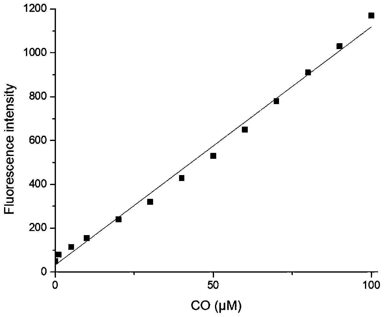
[0033] figure 2 Fluorescence spectra of the interaction between fluorescent probe and CO, fluorescent probe and Pd 2+ The concentration of CO is 10μM, and the concentration of CO is 0,1,5,10,20,30,40,50,60,70,80,90,100μM. The excitation wavelength used in the experiment is 598nm, and the emission wavelength range is 650-900nm. The slit width is 10.0nm / 10.0nm, and the fluorescence measuring instrument used is Hitachi F4600 fluorescence spectrophotometer. From figure 2 It can be seen that before adding CO, the fluorescent probe is added with Pd due to the quenching effect of allyl formate. 2+ After that, there is no obvious near-infrared emission peak at near-infrared (762nm); Pd is added at the same time 2+ After CO and CO, a clear near-infrared emission peak appeared at 762nm. This is because of Pd 2+ First reduced by CO to Pd 0 , Which then mediates the Tsuj
PUM
 Abstract
Description
Claims
Application Information
 - R&D Engineer
- R&D Manager
- IP Professional
- Industry Leading Data Capabilities
- Powerful AI technology
- Patent DNA Extraction
Browse by: Latest US Patents, China's latest patents, Technical Efficacy Thesaurus, Application Domain, Technology Topic.
© 2024 PatSnap. All rights reserved.Legal|Privacy policy|Modern Slavery Act Transparency Statement|Sitemap