Door closer with tri-lobe pinion

a tri-lobe pinion and door closer technology, applied in the field of door closers, can solve the problems that the installer of the door closer may have difficulty in identifying the correct orientation, and achieve the effect of reducing the number of incorrect shaft/arm mounting orientations

Inactive Publication Date: 2015-07-30
STANLEY SECURITY SOLUTIONS
View PDF13 Cites 24 Cited by
  • Summary
  • Abstract
  • Description
  • Claims
  • Application Information

AI Technical Summary

Benefits of technology

The inventor describes an improved way to attach different parts on doors with accurate gear arrangements by providing a special feature called this new design. This makes it easier than previous designs because they only require one orientation from which all components are attached.

Problems solved by technology

This technical problem addressed in this patents relating to improving the efficiency at which doors close without excessive force on their users' hands due to poor alignment between the main latcher arm and its corresponding mountings.

Method used


Image

  • Door closer with tri-lobe pinion
  • Door closer with tri-lobe pinion
  • Door closer with tri-lobe pinion

Examples


Embodiment Construction

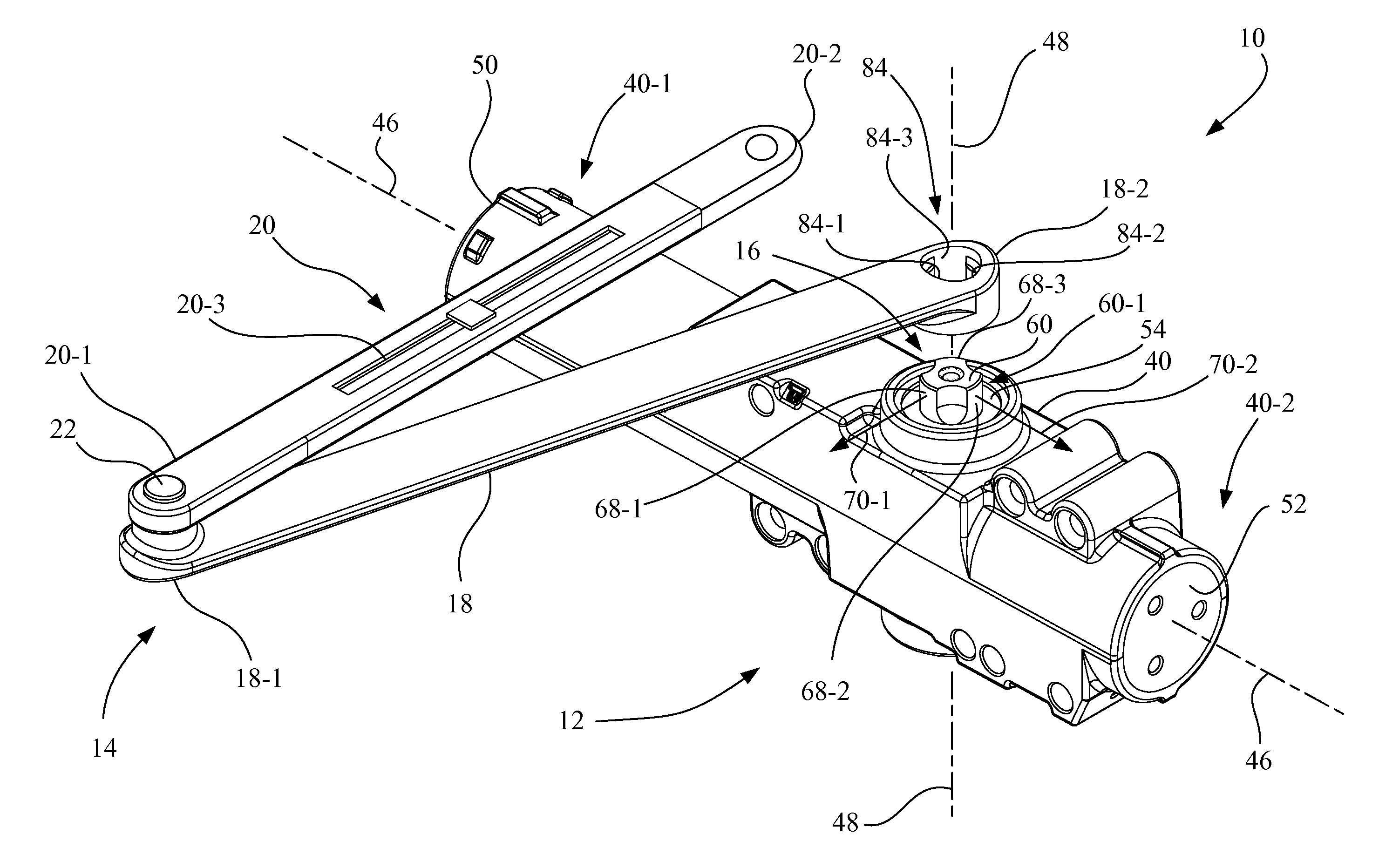
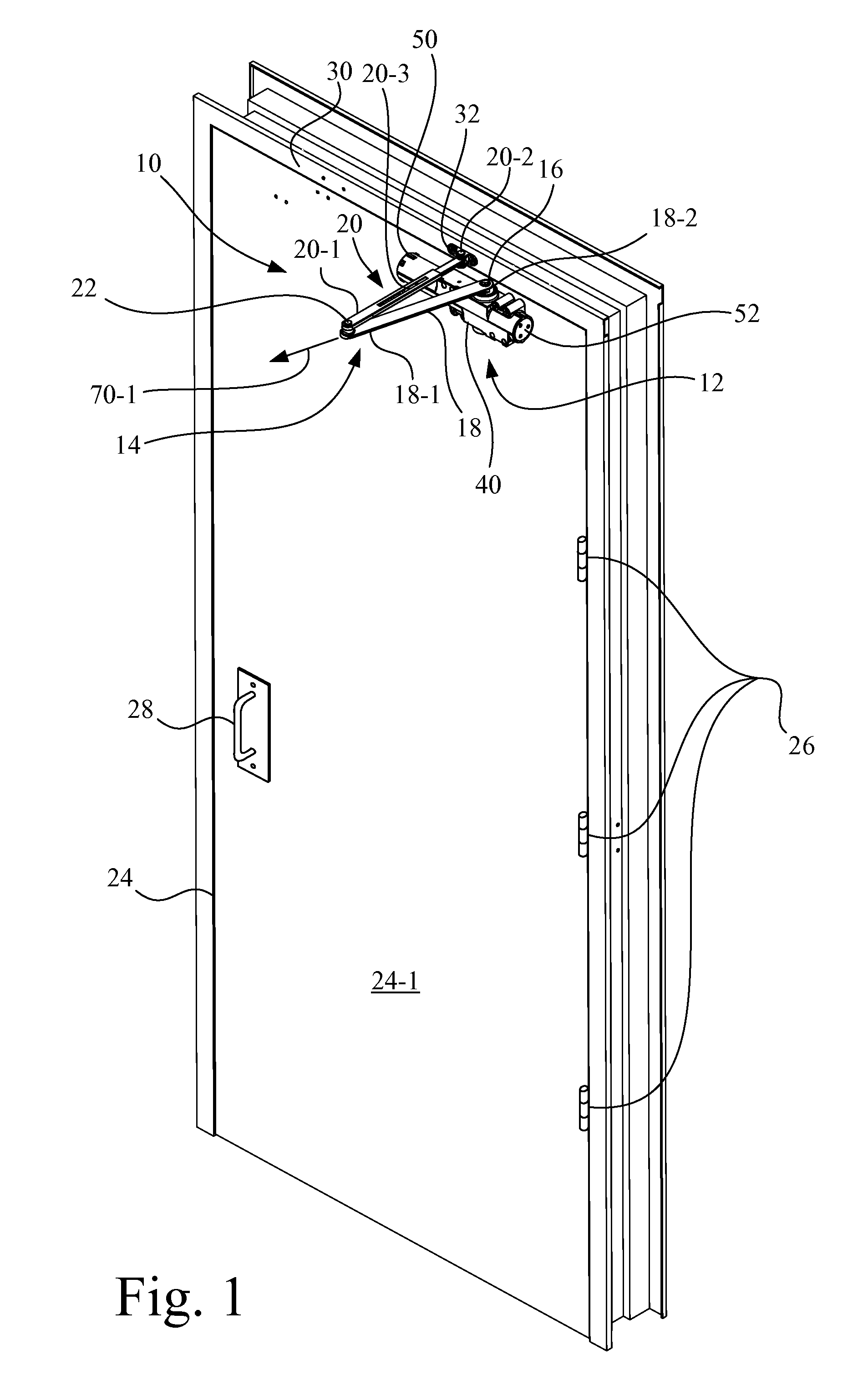
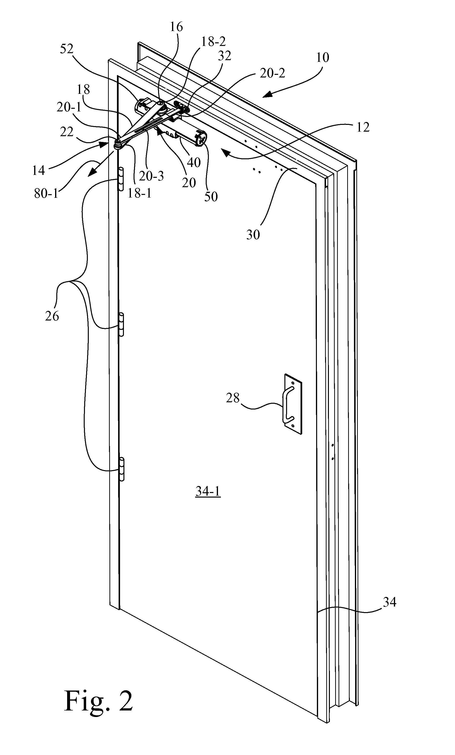
[0032]Referring now to the drawings and particularly to FIGS. 1-4, there is shown a door closer assembly 10 of the present invention, including a door closer 12 and a door closer arm assembly 14. Door closer 12 includes a rotatable pinion 16. Door closer arm assembly 14 is in the form of an articulating linkage that includes a main closer arm 18 and a secondary closer arm 20.

[0033]Main closer arm 18 and a secondary closer arm 20 are pivotally joined at respective ends 18-1, 20-1 at a pivot joint 22. Pivot joint 22 may be, for example, a pin / hole arrangement. A mounting end 18-2 of the main closer arm 18 is connected to pinion 16 of the door closer 12. Secondary closer arm 20 has a mounting end 20-2, and may have a length adjustment mechanism 20-3. Length adjustment mechanism 20-3 may be, for example, in the form of a pair of adjustable slide bars, as in the embodiment shown, or may be a threaded rod / nut, or turnbuckle, type of arrangement.

[0034]Referring to FIG. 1, door closer asse


PUM


Abstract

A door closer assembly is configured to controllably close a door and to accommodate several door closer assembly installation configurations. The door closer assembly includes a housing that carries a pinion having a pinion shaft with a tri-lobe end portion. A closer arm having a tri-lobe opening is configured to receive the tri-lobe end portion of the pinion shaft in driving engagement. The tri-lobe end portion of the pinion shaft and the corresponding tri-lobe opening in the closer arm cooperate to limit the number of orientations that the closer arm may be connected to the pinion shaft.

Description


Claims


Application Information

Patent Timeline
Owner STANLEY SECURITY SOLUTIONS
Why Eureka
Try Eureka