Sensing amplifier utilizing bit line clamping devices and sensing method thereof

Inactive Publication Date: 2015-10-01
BRIDGESTONE CORP
View PDF13 Cites 9 Cited by
  • Summary
  • Abstract
  • Description
  • Claims
  • Application Information

AI Technical Summary

Benefits of technology

[0024]According to the present invention, the non-pneumatic tire can be

Problems solved by technology

In a pneumatic tire of the related art that is filled with pressurized ai

Method used


Image

  • Sensing amplifier utilizing bit line clamping devices and sensing method thereof
  • Sensing amplifier utilizing bit line clamping devices and sensing method thereof
  • Sensing amplifier utilizing bit line clamping devices and sensing method thereof

Examples


Example

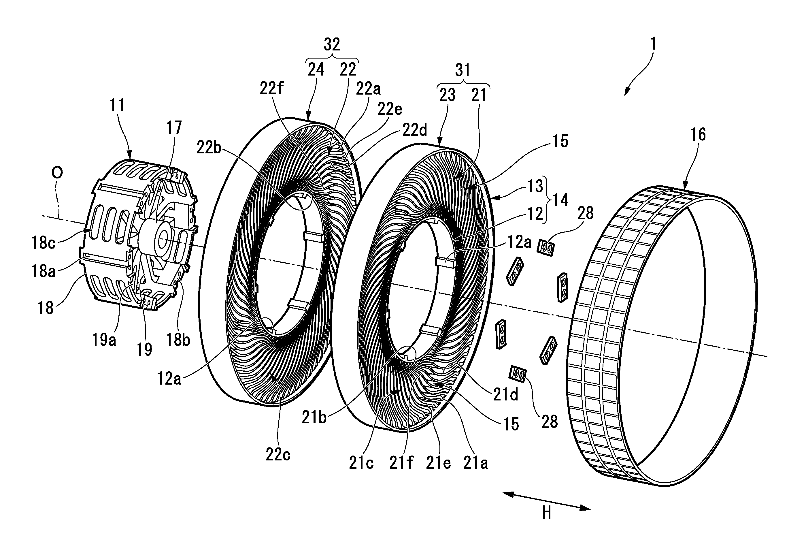
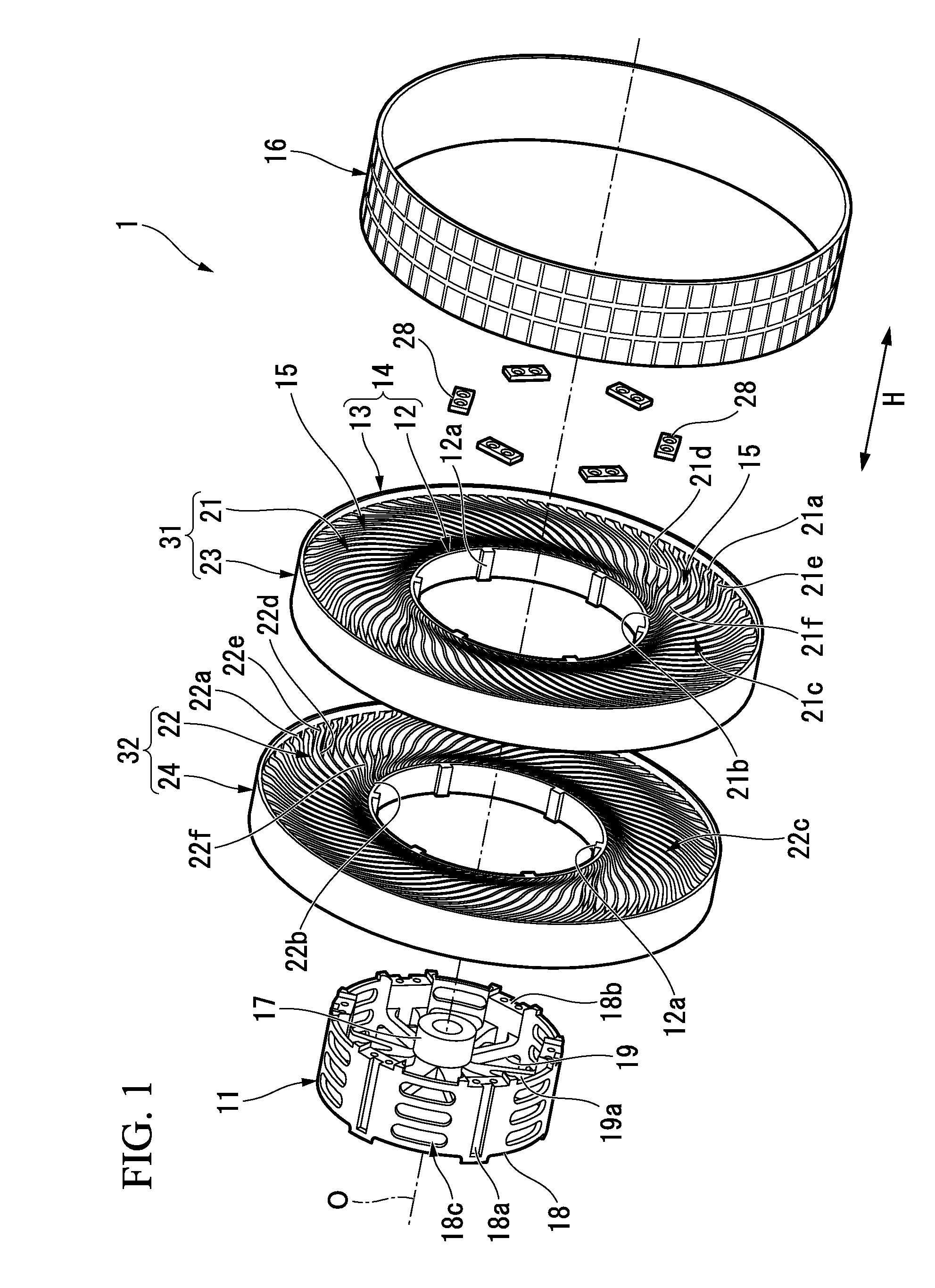
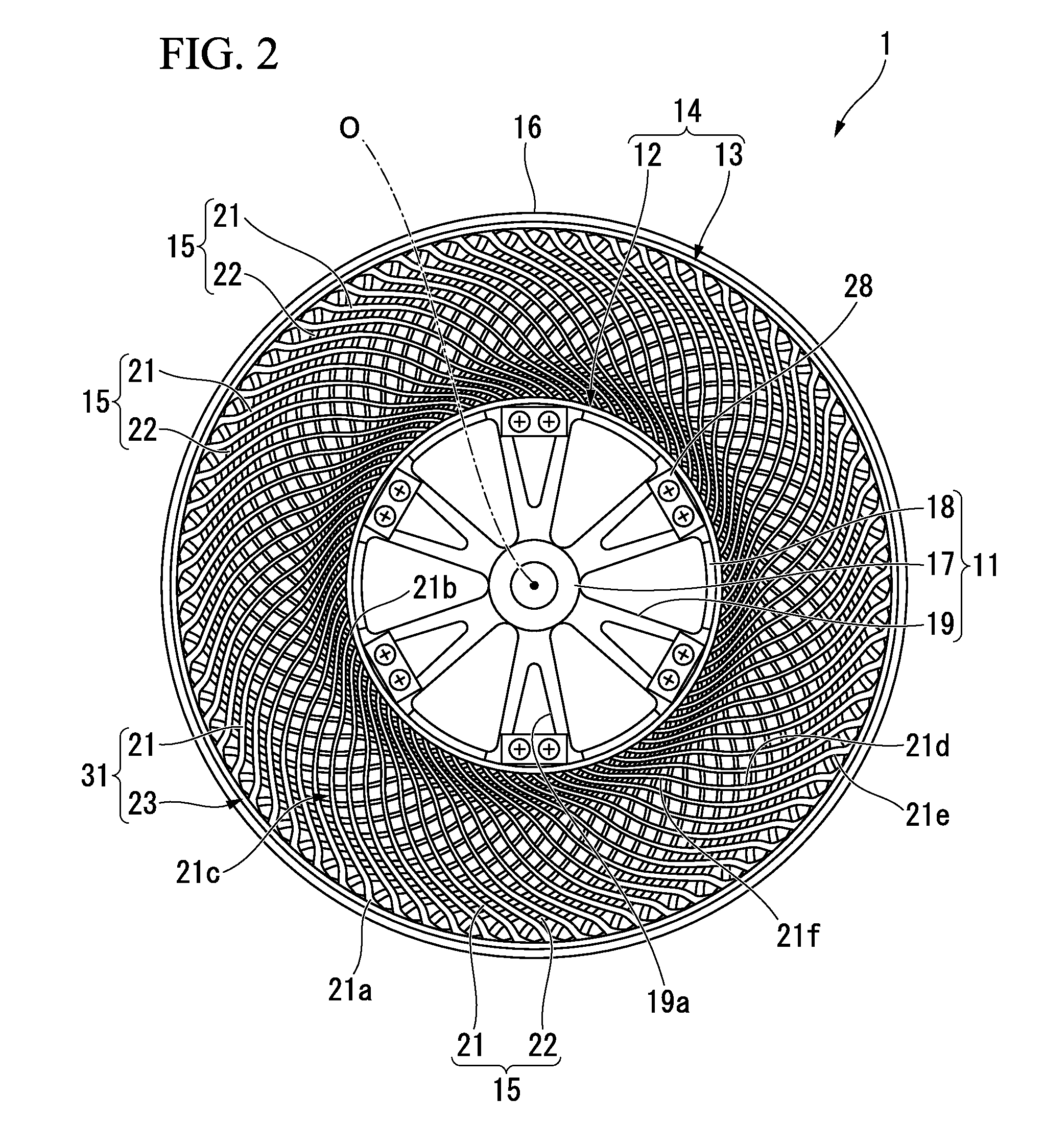
[0029]Hereinafter, an embodiment of a non-pneumatic tire according to the present invention will be described with reference to FIGS. 1 to 4.

[0030]A non-pneumatic tire 1 includes an attachment body 11 attached to an axle (not shown), a ring member 14 including an inner rim 12 fitted onto the attachment body 11 and an outer rim 13 configured to surround the inner rim 12 from the outside in a tire radial direction, a plurality of connecting members 15 disposed between the inner rim 12 and the outer rim 13 in a tire circumferential direction and configured to connect the rims 12 and 13 to each other in a relatively elastically displaceable manner, and a tread member 16 disposed at an outer circumferential surface side of the outer rim 13 throughout the entire circumference.

[0031]Here, the attachment body 11, the inner rim 12, the outer rim 13, and the tread member 16 are disposed on the same axis as a common axis. Hereinafter, the common axis is referred to as an axis O, a direction along


PUM


Abstract

A non-pneumatic tire includes an attachment body (11) attached to an axle, a ring member (14) including an inner rim (12) fitted onto the attachment body (11) and an outer rim (13) configured to surround the inner rim (12) from the outside in a tire radial direction, and a plurality of connecting members (15) disposed between the inner rim (12) and the outer rim (13) in a tire circumferential direction and configured to connect the rims (12) and (13) to each other, wherein at least a portion of the ring member (14) and the plurality of connecting members (15) are integrally formed of a synthetic resin material having a bending modulus of elasticity obtained through a 3-point bending test pursuant to ISO 178 of 300 MPa or more and a Charpy impact value obtained at 23° C. through a Charpy impact test pursuant to ISO 179-1 of 5 kJ/m2 or more.

Description


Claims


Application Information

Patent Timeline
Owner BRIDGESTONE CORP
Why Eureka
Try Eureka