Method for disassembling and/or assembling an underwater section of a retractable thruster unit

Active Publication Date: 2015-11-19
KONGSBERG MARITIME FINLAND OY
View PDF12 Cites 7 Cited by
  • Summary
  • Abstract
  • Description
  • Claims
  • Application Information

AI Technical Summary

Benefits of technology

[0008]Several advantages over prior art are attainable by the present invention. The inventive method is applicable both for new building installations and for already installed thrusters. Docking is not required for preparations for the method. Because docking is not required the out-of-service time of the vessel is shorter than before and the expenses relating to the dismounting/mounting work are lower.

Problems solved by technology

Dry docking of a vessel is extremely expensive because the work itself on a dry dock is expensive and the preparations for taking a vessel to a dry dock are time consuming.
Out-of-service time of a large vessel may become quite long and that costs money.

Method used


Image

  • Method for disassembling and/or assembling an underwater section of a retractable thruster unit
  • Method for disassembling and/or assembling an underwater section of a retractable thruster unit
  • Method for disassembling and/or assembling an underwater section of a retractable thruster unit

Examples


Example

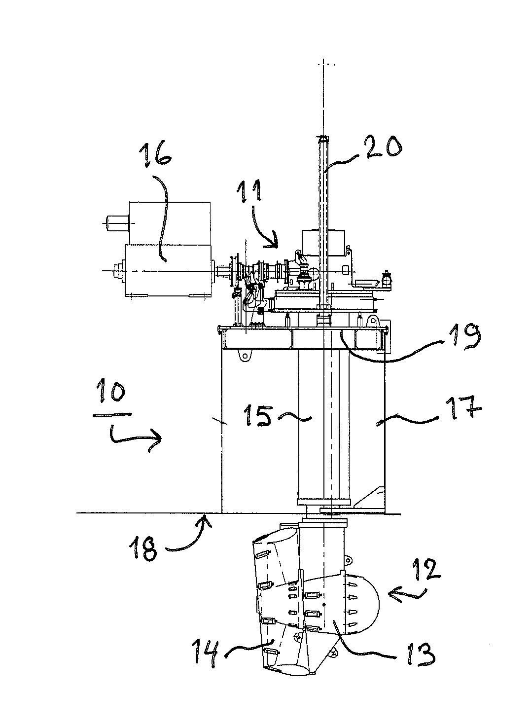
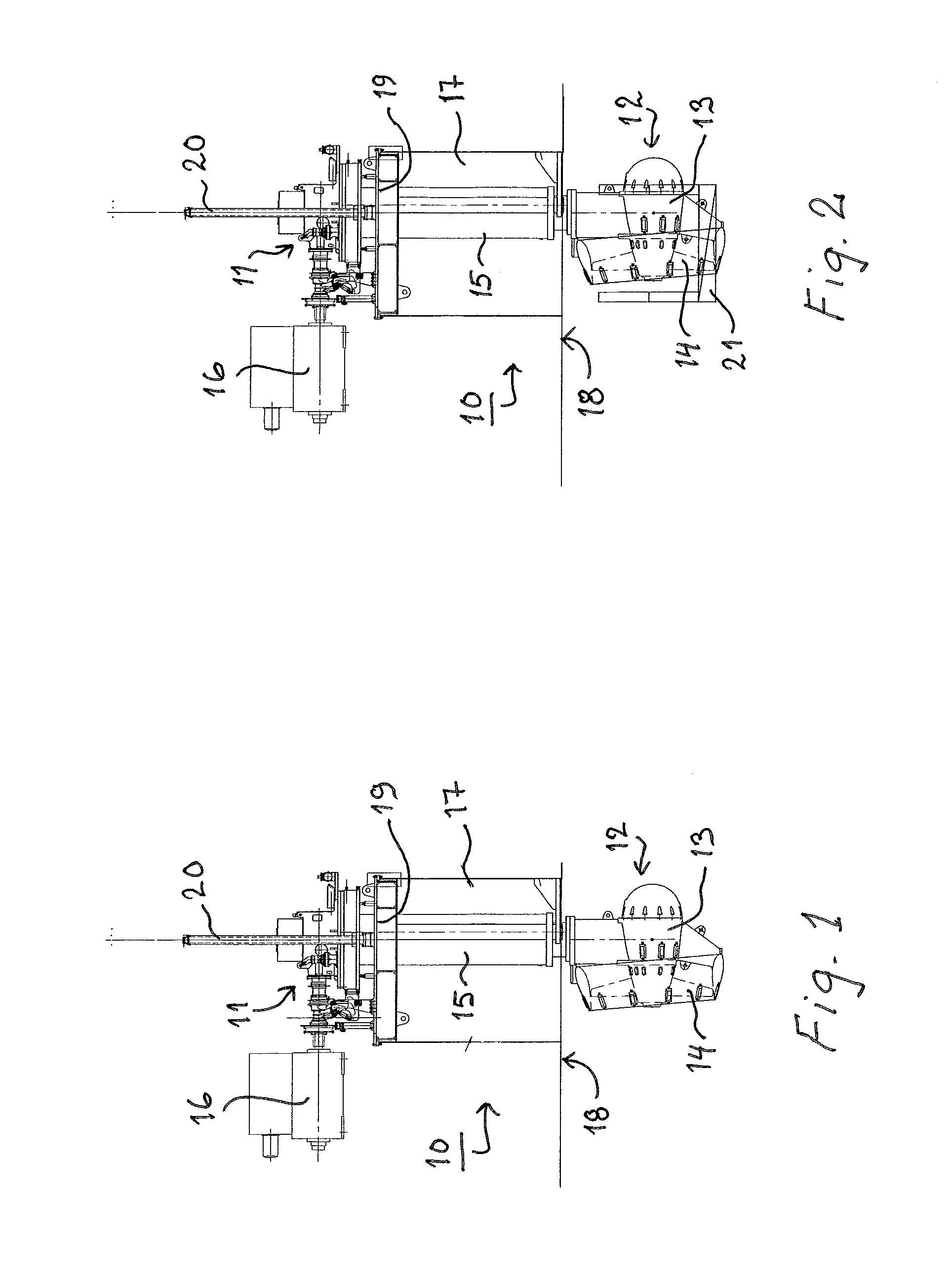
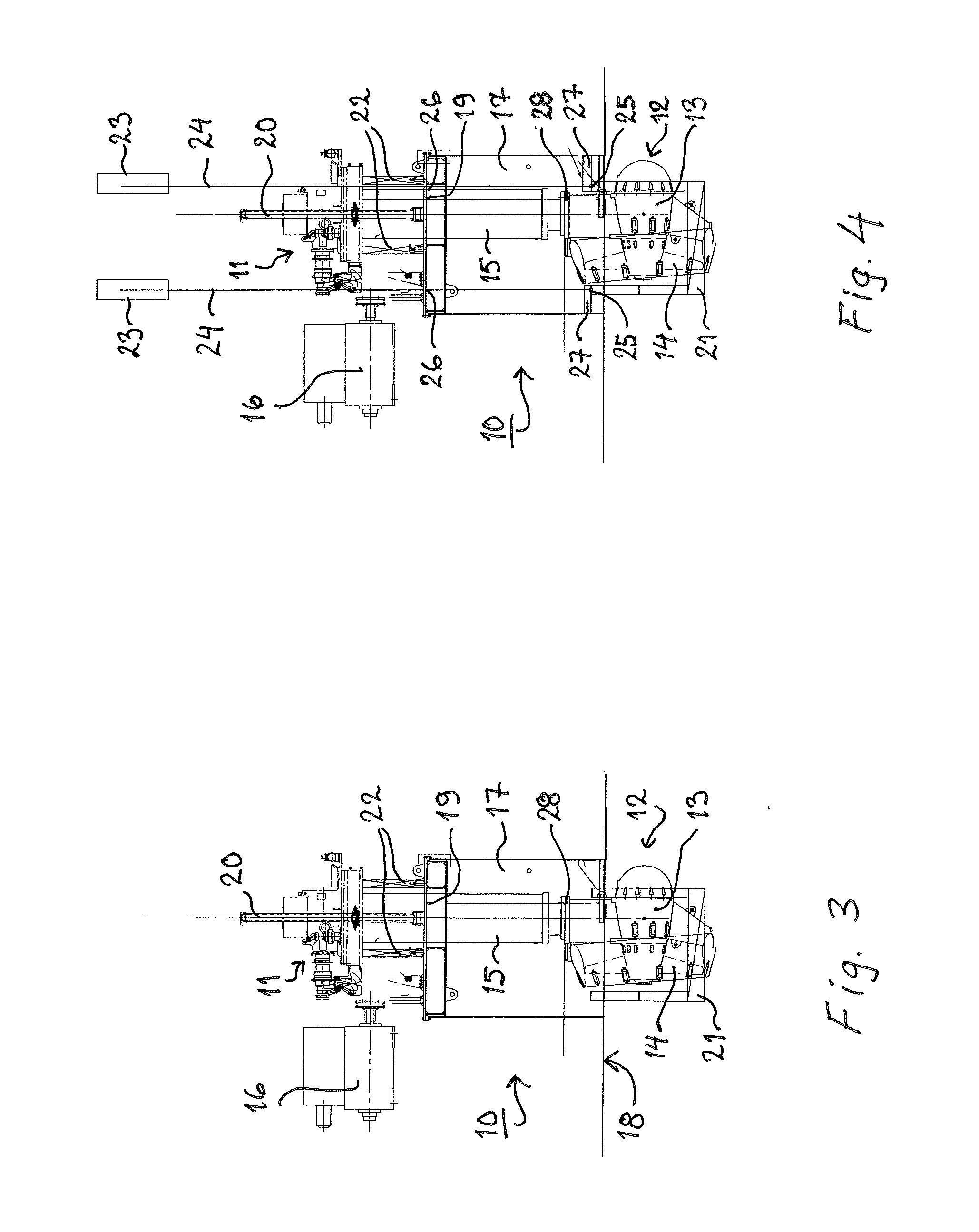
[0017]FIG. 1 shows an azimuthing thruster unit 10 which is turnable around a vertical axis for steering. The thruster unit 10 comprises an upper gear 11 connected to a power source 16, an underwater section 12 including a lower gear 13 connected to the actual propeller 14, and a vertical steering tube 15 connecting the upper gear 11 with the lower gear 13. Said steering tube 15 contains a vertical shaft through which power and torque are transmitted from the upper gear 11 to the lower gear 13.

[0018]The thruster unit 10 is mounted in a swimming vessel so that a well 17 is formed in the bottom 18 of the vessel. The well 17 is open downwards but the top of the well is provided with a covering plate 19 by which the well 17 is sealed and closed upwards. As shown in the drawings the upper gear 11 of the thruster unit 10 is placed above the covering plate 19 which is provided with a sealed lead-in through which the vertical steering tube 15 extends from the upper gear 11 to the lower gear 13


PUM

PropertyMeasurementUnit
Diameteraaaaaaaaaa

Abstract

A method for disassembling and/or assembling an underwater section of a retractable thruster unit of a swimming vessel. A supporting cradle is detachably fixed to the underwater section from below, and the thruster unit is lifted so that the underwater section is at least partly brought inside the well formed in the bottom of the vessel. Lifting wires of an auxiliary lift are connected to the supporting cradle for supporting the thruster unit. Water is drained from the well, and the lower gear is disengaged and the intermediate section and the lower gear are sealed. After that water is let to ingress into the well and the underwater section is lowered down by the auxiliary lift to dock bottom or sea bed, from where the underwater section is picked up with a crane.

Description


Claims


Application Information

Patent Timeline
Owner KONGSBERG MARITIME FINLAND OY
Why Eureka
Try Eureka