Valve gear for engine

a valve gear and engine technology, applied in the direction of valve details, valve arrangements, machines/engines, etc., can solve the problems of difficult to guarantee performance, difficult to replace, and the above-mentioned camshaft phase varying device cannot operate satisfactorily, so as to improve the abrasion resistance of the constituent components, easy replacement, and easy replacement

Active Publication Date: 2016-01-14
SUZUKI MOTOR CORP
View PDF0 Cites 6 Cited by
  • Summary
  • Abstract
  • Description
  • Claims
  • Application Information

AI Technical Summary

Benefits of technology

The present invention provides a way to ensure stable operation of a cam shaft phase changing device by supplying engine oil to specific parts of the device while ensuring smooth rotation of the valve timing changes without causing damage. This improves wear-resistance and maintains good overall performance.

Problems solved by technology

This patent describes a problem where different timing adjustments made during operation of engines have resulted from changes in the operating conditions of the engine. Specifically, this issue arises because conventional valve gears used in these engines only allow for independent movement of their own components without affecting the timing of the valves' optimal openings and closures.

Method used


Image

  • Valve gear for engine
  • Valve gear for engine
  • Valve gear for engine

Examples


Embodiment Construction

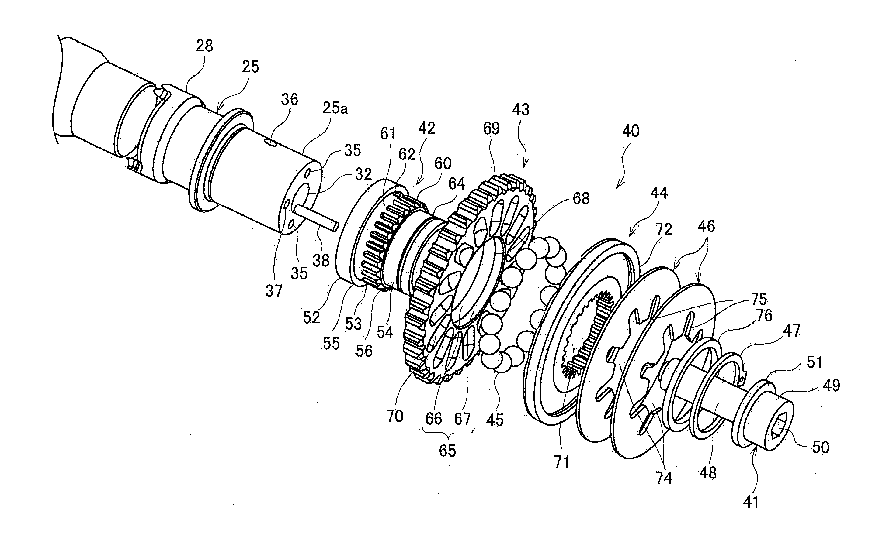
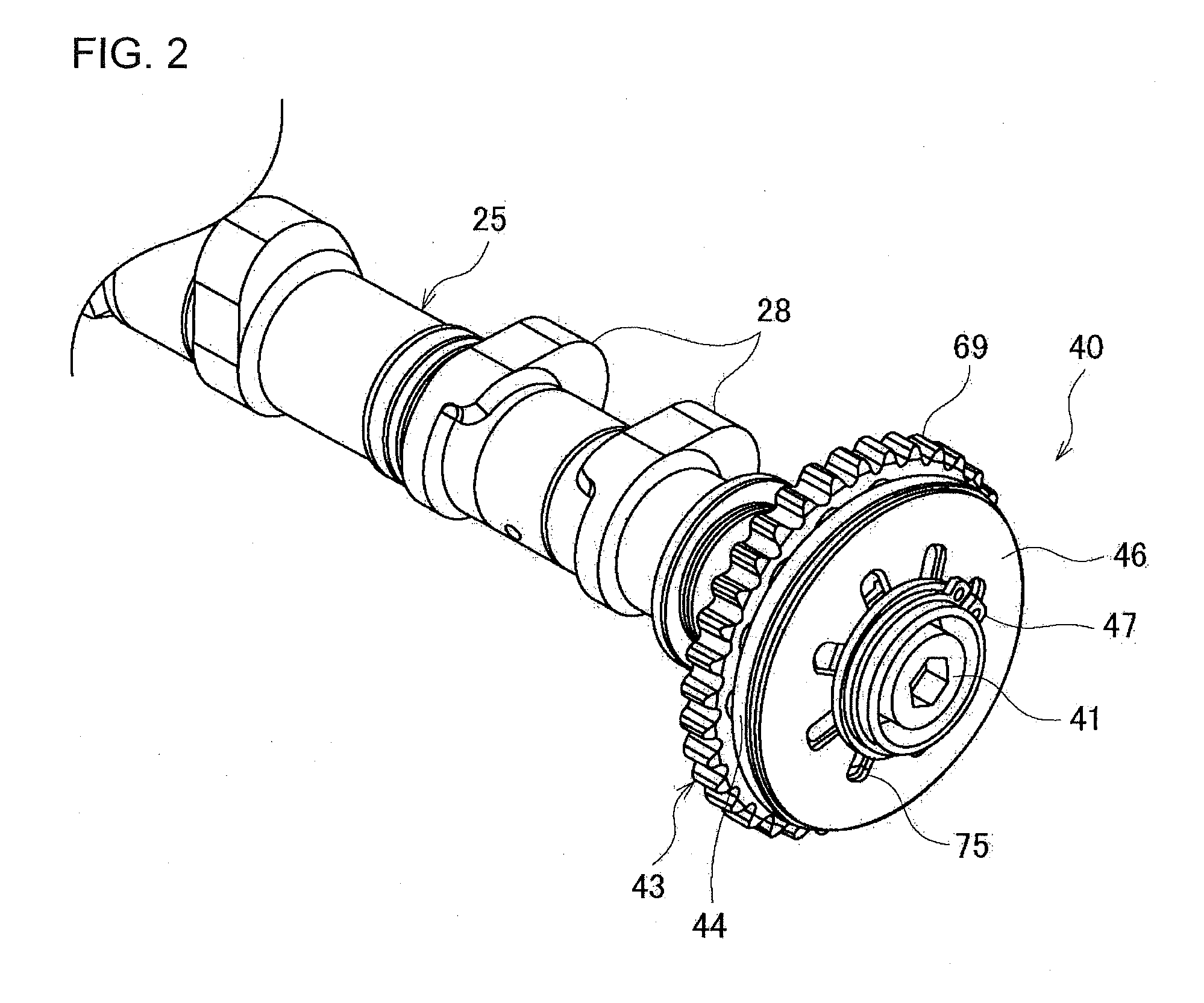
[0043]A valve gear for an engine according to an embodiment of the invention will be described below with reference to the drawings.

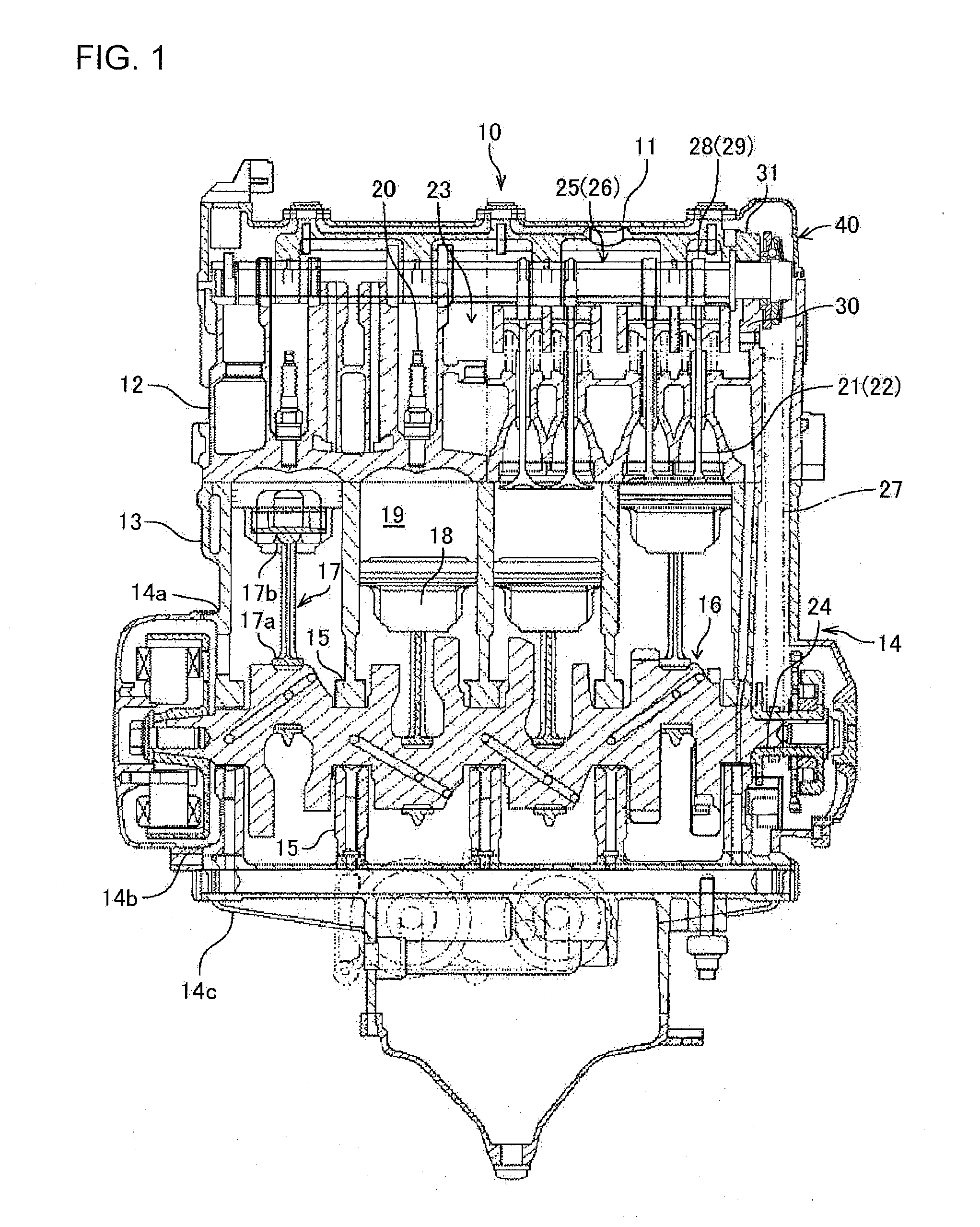
[0044]First, an engine provided with a valve gear according to an embodiment of the invention will be described with reference to FIG. 1. FIG. 1 is a sectional view showing the engine provided with the valve gear according to the embodiment of the invention.

[0045]An engine 10 is, for example, a 4-cycle parallel four cylinder engine, which is mainly constituted by a head cover 11, a cylinder head 12, a cylinder block 13 and an engine case 14. The engine case 14 is vertically divided into three, including an upper engine case 14a, a center engine case 14b and a lower engine case 14c. The cylinder block 13 is formed integrally with the upper engine case 14a.

[0046]The cylinder block 13 is disposed not upright but slightly with a forward inclination. Each of bearing portions 15 is formed to be divided into upper and lower parts on the inner sides of mating sur


PUM


Abstract

A valve gear for an engine, includes: a camshaft phase varying device by which a rotational phase of a camshaft for opening/closing valves of the engine can be changed relatively to that of a crankshaft; and a holder that is provided so that the holder can be removably attached to the camshaft in a state where the holder has held constituent components of the camshaft phase varying device.

Description


Claims


Application Information

Patent Timeline
Owner SUZUKI MOTOR CORP
Why Eureka
Try Eureka