Pre-emptive overhead message reading

a pre-emptive overhead message and message technology, applied in the field of wireless communication, can solve problems such as service disruption for users

Inactive Publication Date: 2016-03-17
QUALCOMM INC
View PDF6 Cites 9 Cited by
  • Summary
  • Abstract
  • Description
  • Claims
  • Application Information

AI Technical Summary

Benefits of technology

This patented technology allows users to request an upcoming call from their mobile device when they have no better way than usual by monitoring its own signal quality before connecting back again after being disconnected from that base station. By doing this, it can improve network efficiency and reduce delays caused during calls made over wireless networks like LTE.

Problems solved by technology

The technical problem addressed in this patented technology relates to improving mobile device battery life during times of consistently low signal quality due to frequent reconnect attempts caused by an abrupt loss or other event like Radio Link Failure (RFL).

Method used


Image

  • Pre-emptive overhead message reading
  • Pre-emptive overhead message reading
  • Pre-emptive overhead message reading

Examples


Embodiment Construction

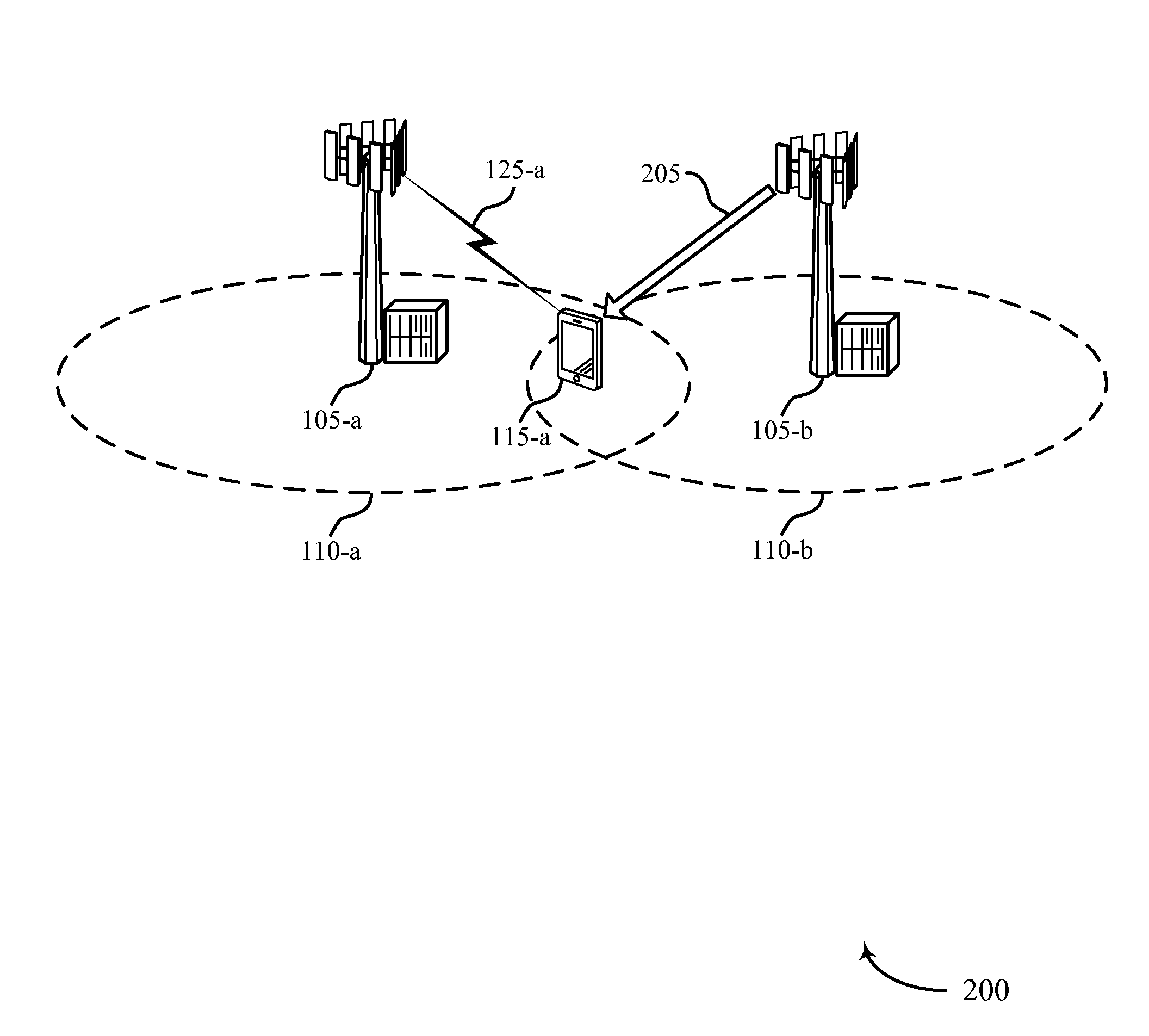
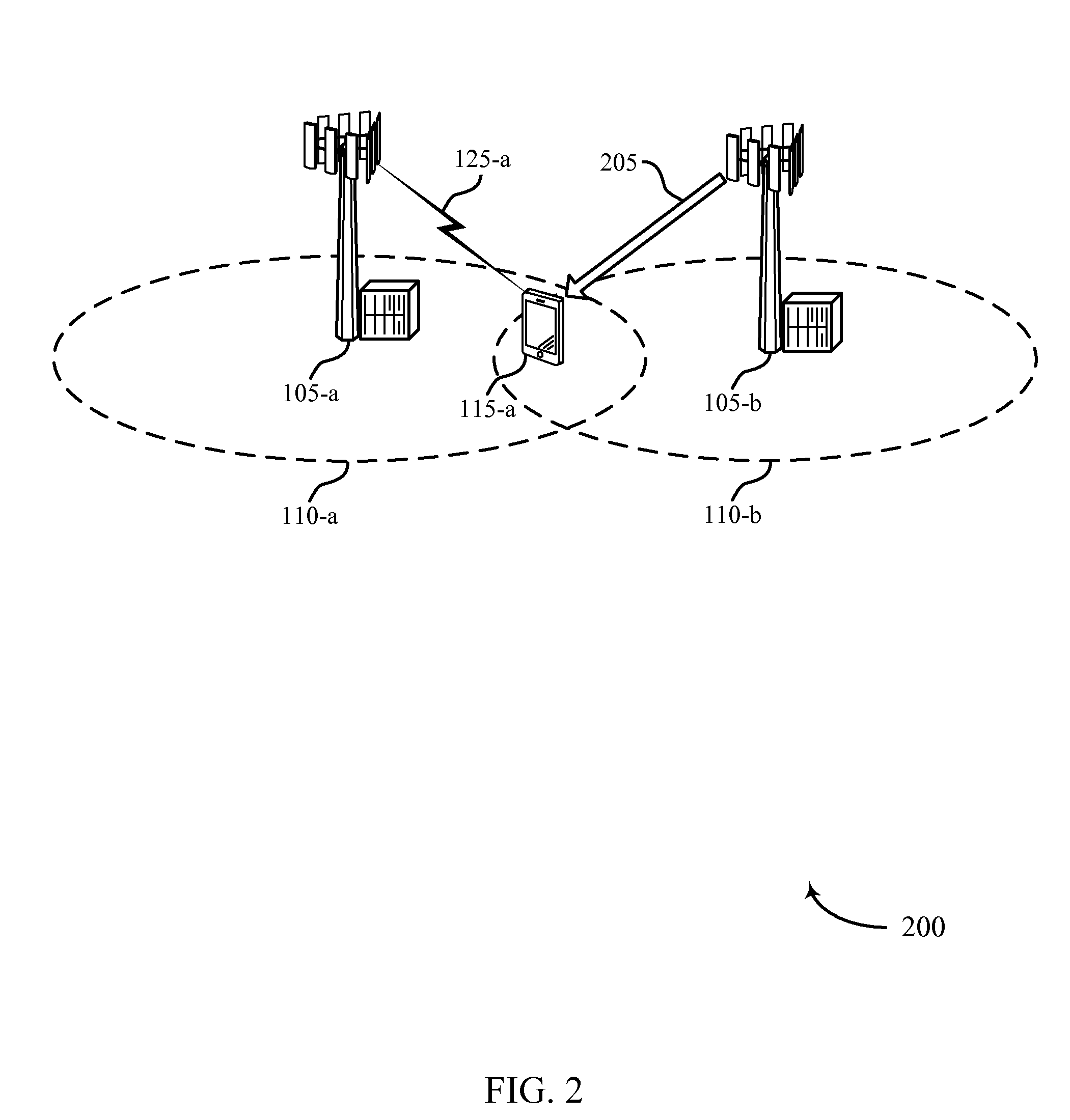
[0035]A user equipment (UE) may monitor channel conditions for a serving cell and non-serving neighboring cells. The UE may determine to read the system information of a non-serving neighbor when certain channel conditions exist, or when certain performance metrics are unsatisfied. The UE may then read the system information of the non-serving neighbor cell while still connected to the serving cell (e.g., prior to handover). In some cases, the UE may store the system information in a database. Then if and when the UE attempts to access a neighbor cell (e.g., if the link to the serving cell fails) the UE may use the stored system information, and proceed with access procedures without delay.

[0036]Thus, in cases when a UE experiences a radio link failure (RLF) or handover, the UE may establish a new connection without attempting to read the system information of the neighboring (e.g., target) cell. This may reduce the delay in a connection reestablishment and / or mobility procedure, and


PUM


Abstract

Methods, systems, and devices are described for wireless communication at a UE. A user equipment (UE) may establish a connection to a serving cell and monitor channel conditions for the serving cell and neighboring cells. Based on the channel conditions, the UE may determine to read the system information of a non-serving neighbor. The UE may then read the system information of the non-serving neighbor cell while still connected to the serving cell. In some cases, the UE may store the system information in a database. When the time comes for the UE to access the neighbor cell (e.g., if the link to the serving cell fails) the UE may proceed with access procedures without delay using the stored system information.

Description


Claims


Application Information

Patent Timeline
Owner QUALCOMM INC
Why Eureka
Try Eureka