Pucch for mtc devices

a technology of machine type communication and control channel, applied in the field of physical uplink control channel (pucch) for machine type communication (mtc) devices, can solve problems such as transmission repeating and transmission collisions

Active Publication Date: 2016-05-12
QUALCOMM INC
View PDF17 Cites 41 Cited by
  • Summary
  • Abstract
  • Description
  • Claims
  • Application Information

AI Technical Summary

Benefits of technology

This patent describes improvements in wireless communication networks that allow people to access their data wirelessly over longer distances without being tied up by long lines. These improvements include improving system performance and reducing power consumption.

Problems solved by technology

The technical problem addressed in this patent text relates to how to efficiently transmit signals between two devices over a wireless network while avoiding collision issues caused by varying radio configuration settings.

Method used


Image

  • Pucch for mtc devices
  • Pucch for mtc devices
  • Pucch for mtc devices

Examples


Embodiment Construction

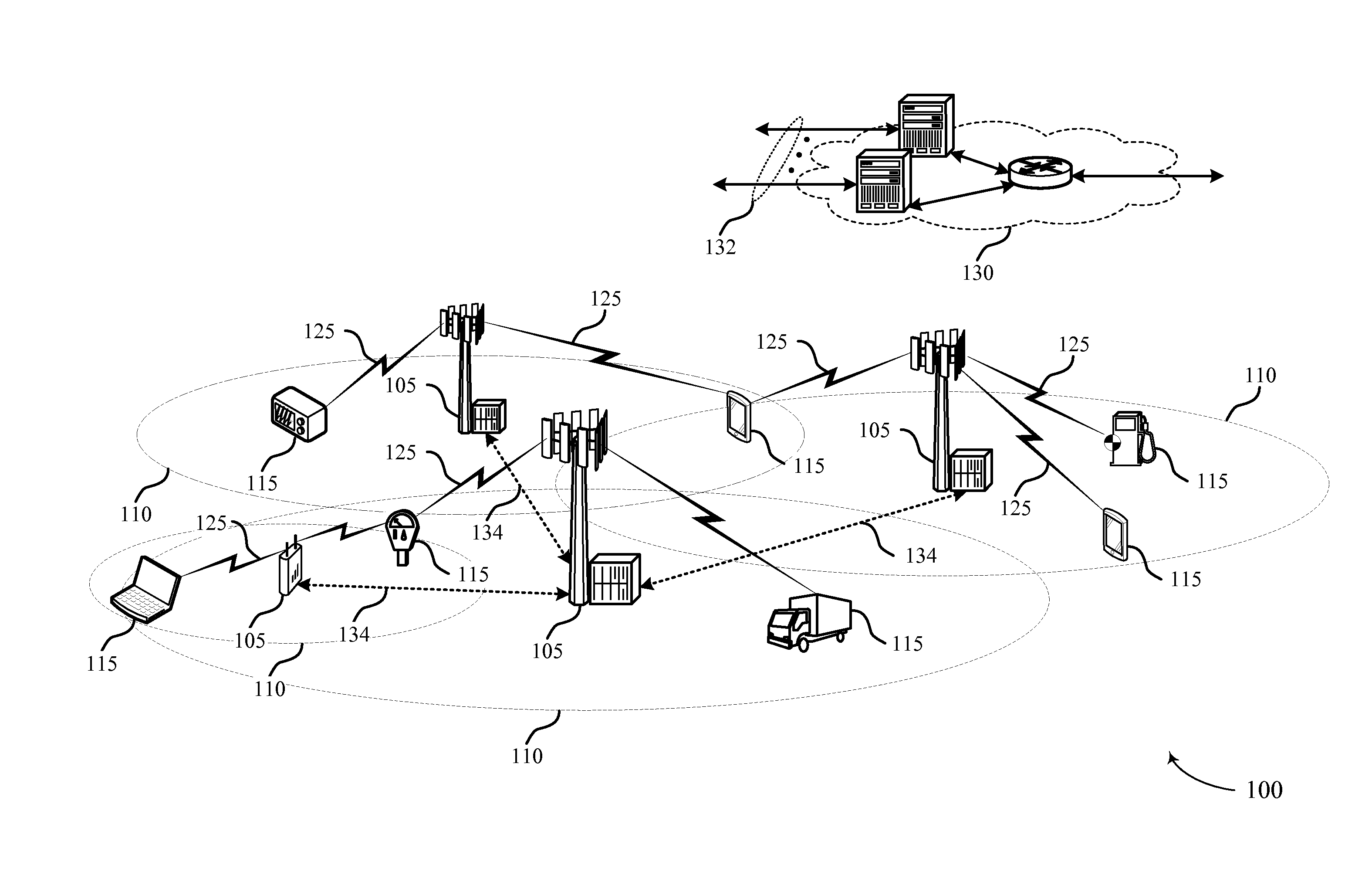
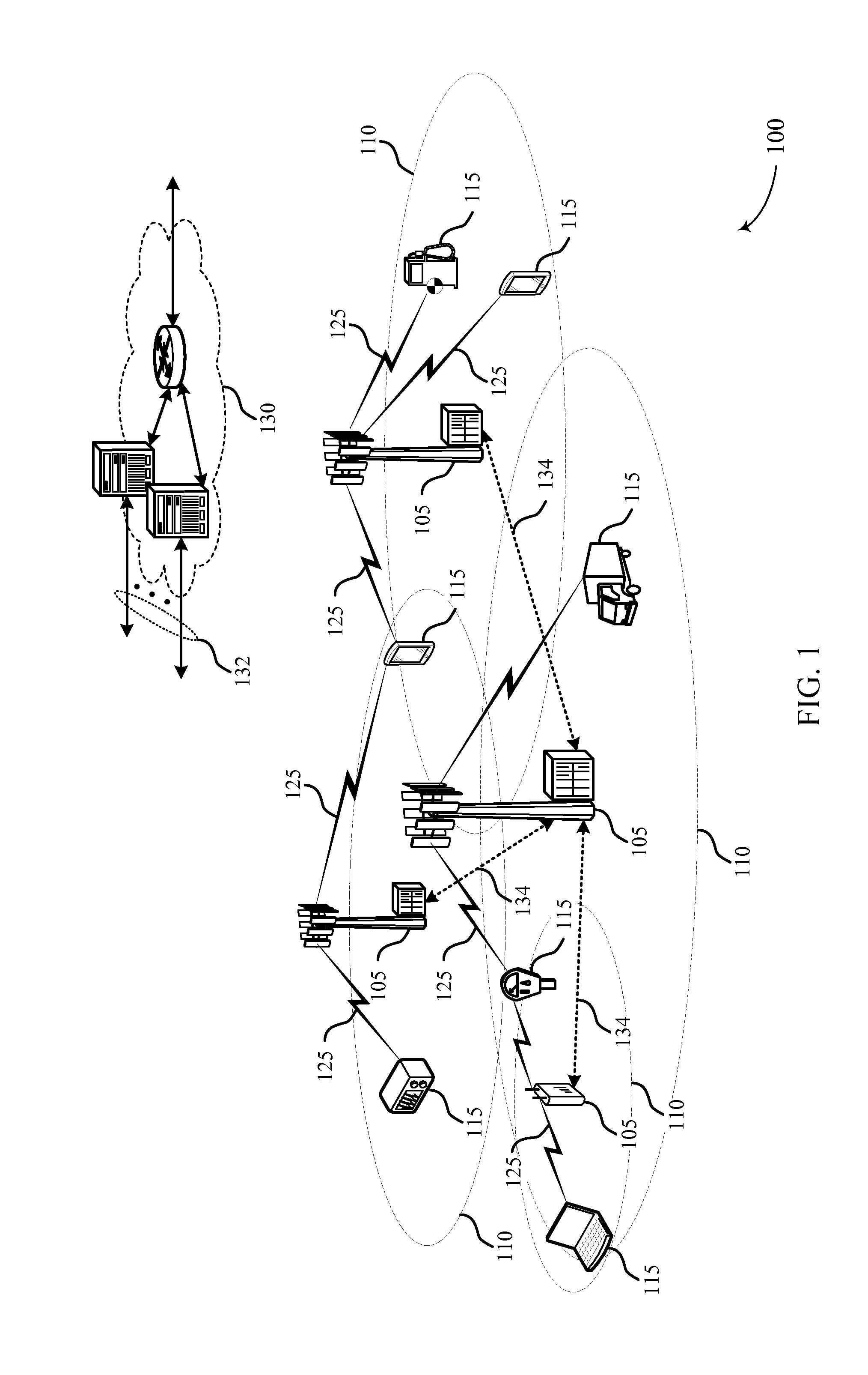
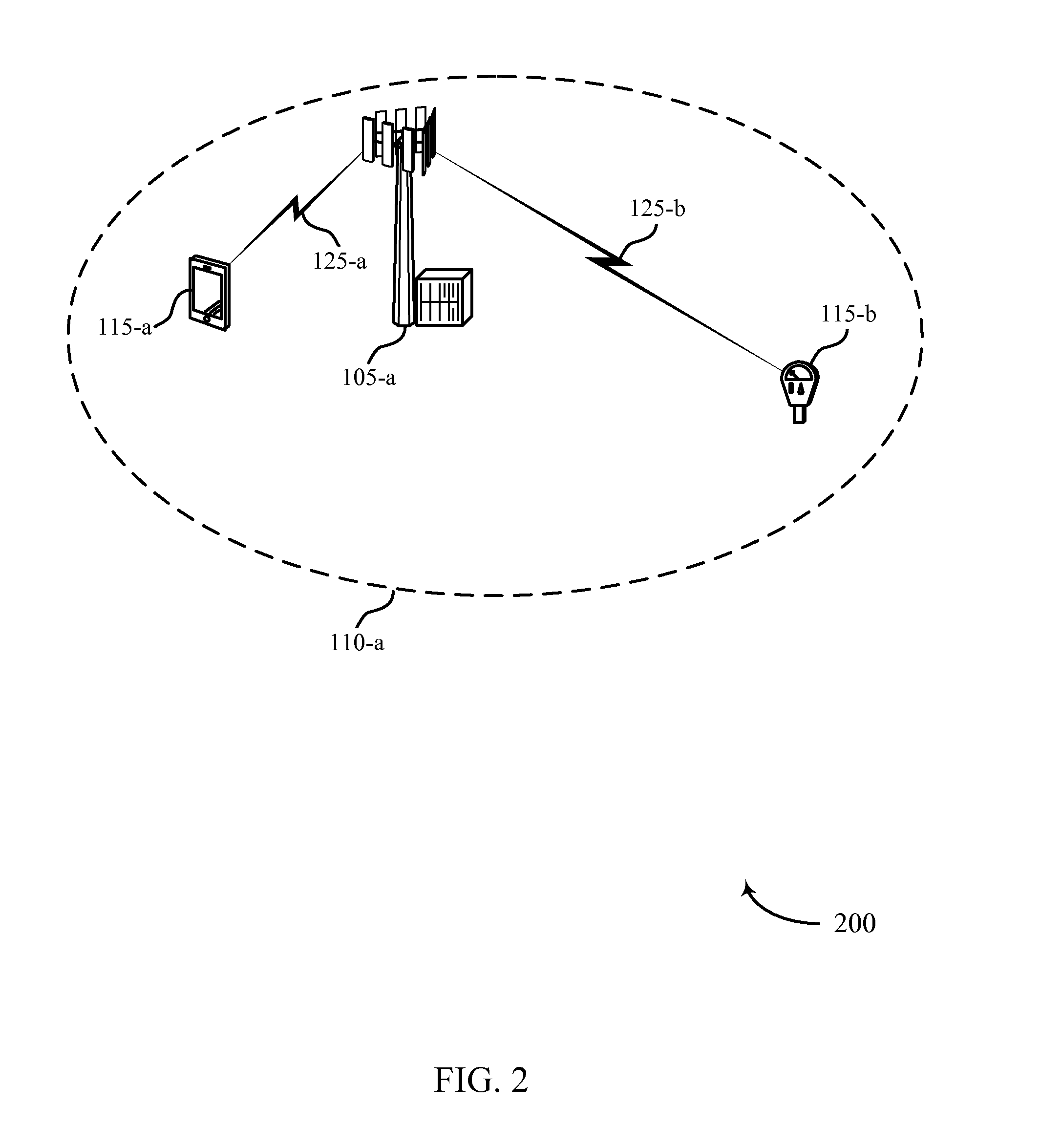
[0046]The described features generally relate to improved systems, methods, or apparatuses for a physical uplink (UL) control channel (PUCCH) with Machine Type Communication (MTC) devices. Some wireless systems may provide for automated communication such as MTC or Machine-to-Machine (M2M) communication. M2M or MTC may refer to technologies that communicate without human intervention. In some cases, MTC devices may have limited capabilities. For example, while some MTC devices may have broadband capacity, other MTC devices may be limited to narrowband communications. This narrowband limitation may, for example, interfere with the ability of an MTC device to receive control channel information using the full bandwidth served by a base station. In some wireless communication systems, such as Long Term Evolution (LTE), an MTC device having limited bandwidth capability (or another device with similar capabilities) may be referred to as a category 0 device.

[0047]In some cases, MTC devices m


PUM


Abstract

Methods, systems, and devices are described for wireless communication at a device. A wireless device may be configured with a transmission time interval (TTI) bundling parameter. The device may then identify one or more resources for an uplink (UL) control channel based on the TTI bundling parameter (e.g., using either an implicit or an explicit indication from another wireless node such as a serving cell of a base station) and transmit the UL control channel using the identified resources. The device may also identify a downlink control information (DCI) format based on the TTI bundling parameter. For example, a resource allocation granularity level may be associated with the bundling parameter, and the length of a DCI field may depend on the resource allocation granularity level.

Description


Claims


Application Information

Patent Timeline
Owner QUALCOMM INC
Why Eureka
Try Eureka