Adjustable Shelving System

Inactive Publication Date: 2016-07-14
SWINGSTOW LLC
View PDF1 Cites 11 Cited by
  • Summary
  • Abstract
  • Description
  • Claims
  • Application Information

AI Technical Summary

Benefits of technology

[0006]An adjustable shelving system according to the present invention includes a base member having a rear portion, a first side portion, and a second side portion arranged in a triangular configuration suitable for use in a corner of a room (i.e. at an intersection of two generally perpendicular walls. A first shelf assembly is pivotally coupled to the first side of the base member and movable between a first rearward configuration perpendicular to the first side portion of the base member and a first forward configuration offset relative to the rearward configuration. A second shel

Problems solved by technology

Unfortunately, multiple shelving units take up a great deal of space as they must be lined up side by side or spaced apart in parallel alignment such that the front of each unit is accessible.
Further, the back of such units are typically not

Method used


Image

  • Adjustable Shelving System
  • Adjustable Shelving System
  • Adjustable Shelving System

Examples


Embodiment Construction

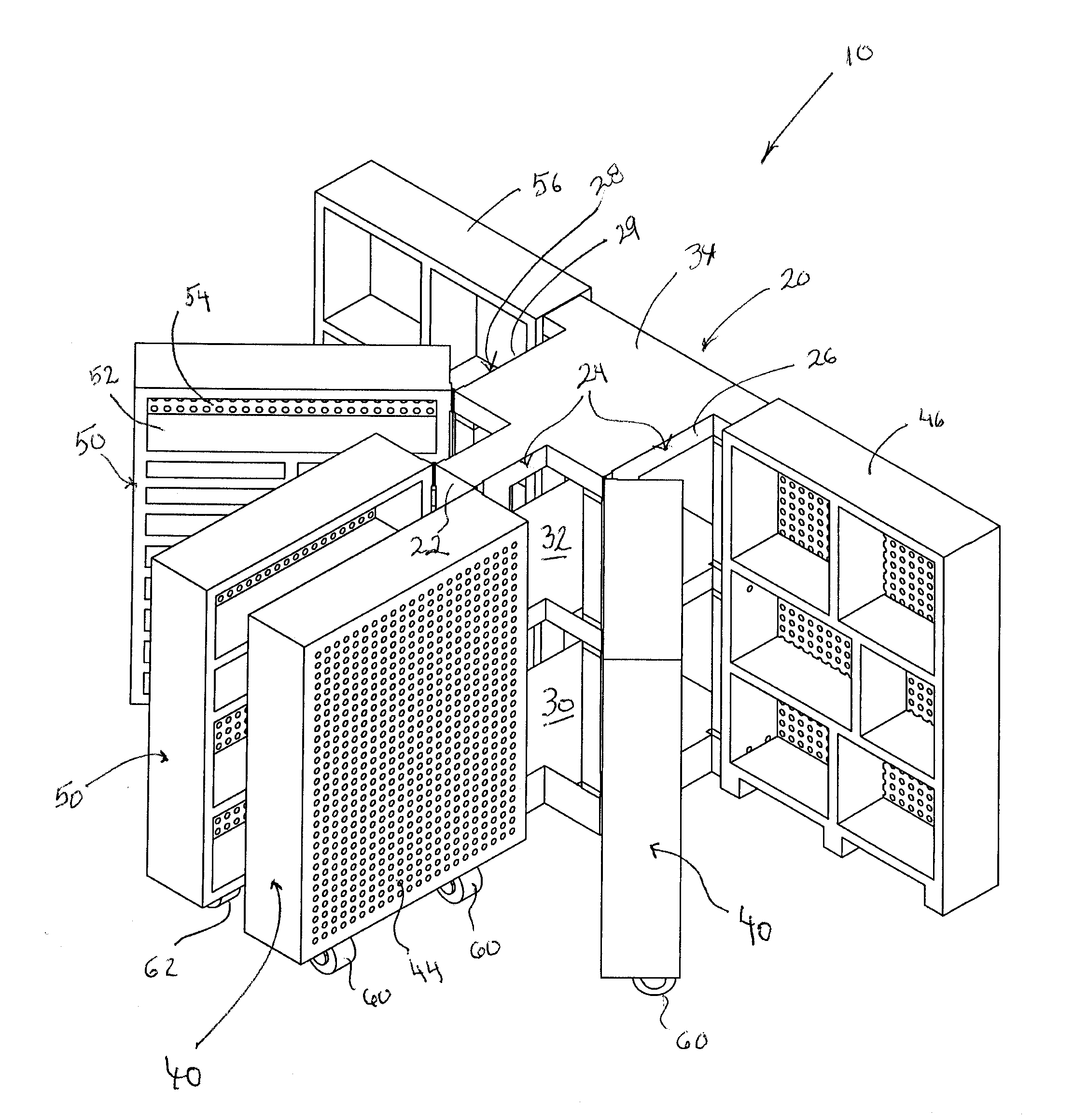
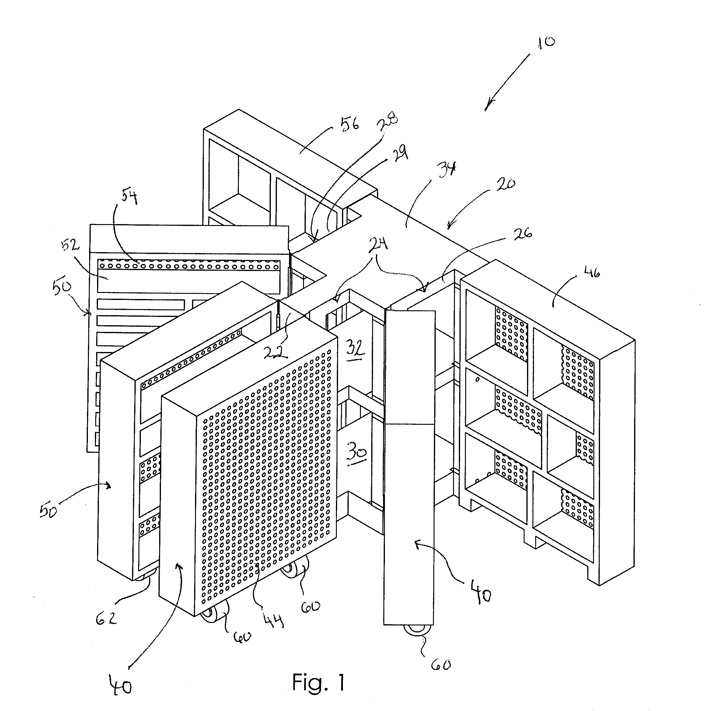
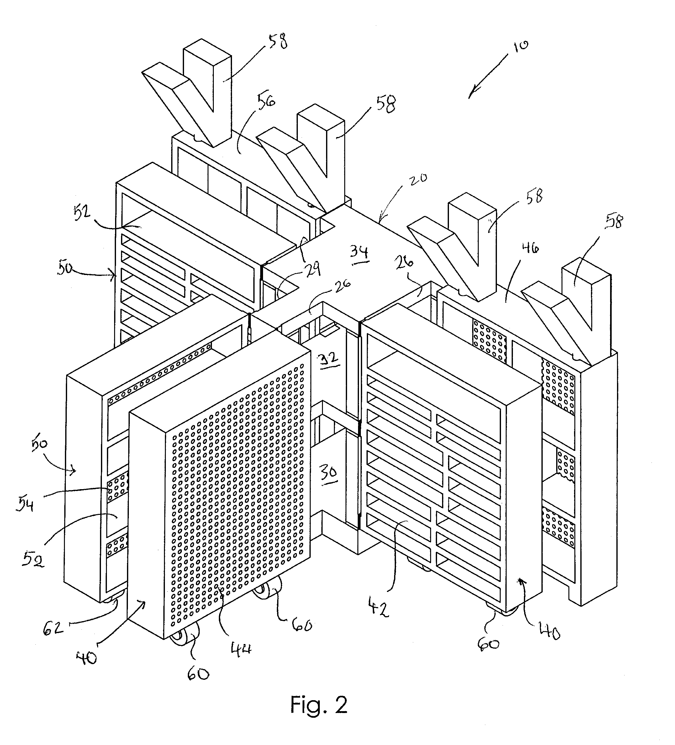
[0036]An adjustable shelving system according to a preferred embodiment of the present invention will now be described in detail with reference to FIGS. 1 to 13b of the accompanying drawings. The shelving system 10 includes a base member 20 (also referred to as a base shelving unit), a plurality of first shelf assemblies 40 pivotally coupled to a first side 24 of the base member 20, and a plurality of second shelf assemblies 50 pivotally coupled to a second side 28 of the base member 20. One or more rollers may be coupled to a bottom surface of each shelf assembly to facilitate movement thereof. Each shelf assembly may be pivotally coupled to the base member 20 with a floating hinge 70 that enables a respective shelf assembly to float upward or downward as it moves on an uneven floor surface or over a small obstacle.

[0037]The base member 20 is a shelving unit having a base portion, intermediate portion, and top portion (FIG. 1). The base member 20 includes a front side, back side, firs


PUM


Abstract

An adjustable shelving system includes a base member having rear, first, and second sides in a triangular configuration suitable for a room corner. A first shelf assembly is pivotally coupled to the first side of the base member and movable between a first rearward configuration perpendicular to the base member and a first forward configuration offset relative to the rearward configuration. A second shelf assembly is pivotally coupled to the second side of the base member and movable between a second rearward configuration perpendicular to the base member and a second forward configuration offset relative to the rearward configuration. Each shelf assembly includes rollers configured to support the weight of the shelf assembly and enhance movement, especially on an uneven surface. Each shelf assembly may include a vertically floatable hinge configured to allow the shelf assembly to move up or down according to changes in elevation of a floor surface.

Description


Claims


Application Information

Patent Timeline
Owner SWINGSTOW LLC
Why Eureka
Try Eureka