Method of forming a composite member and assembly therefor

a composite member and assembly technology, applied in the field of composite component manufacturing, can solve the problems of stringer surface wrinkles or other surface flaws, require relatively complex manipulation,

Inactive Publication Date: 2016-07-28
BOMBARDIER CORP
View PDF4 Cites 16 Cited by
  • Summary
  • Abstract
  • Description
  • Claims
  • Application Information

AI Technical Summary

Benefits of technology

The technical effect of this invention is that it provides better ways to make composites by improving their quality and efficiency during production.

Problems solved by technology

This patent describes a process for making reinforced plates by combining multiple parts without completely hardening them. One part consists of a cylindrical tube filled with air, another part consisting of a breather-lined bag covered on top, and yet another section called a separating membrane between these two parts. When this assembly is done, it can cause issues like wrinkling or defects during curing.

Method used


Image

  • Method of forming a composite member and assembly therefor
  • Method of forming a composite member and assembly therefor
  • Method of forming a composite member and assembly therefor

Examples


Embodiment Construction

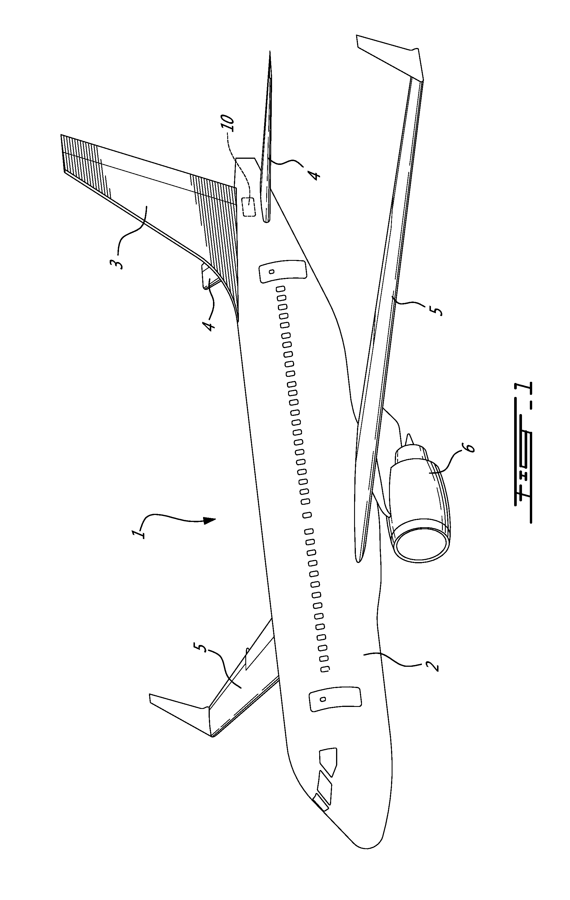
[0034]Referring to the drawings and more particularly to FIG. 1, an aircraft is shown at 1, and is generally described to illustrate some components for reference purposes in the present disclosure. The aircraft 1 has a fuselage 2 having a fore end at which a cockpit is located, and an aft end supporting a tail assembly, with the cabin generally located between the cockpit and the tail assembly. The tail assembly comprises a vertical stabilizer 3 with a rudder, and horizontal stabilizers 4 with elevators. The tail assembly has a fuselage-mounted tail, but other configurations may also be used for the aircraft 1, such as cruciform, T-tail, etc. Wings 5 project laterally from the fuselage. The aircraft 1 has engines 6 supported by the wings 5, although the engines 6 could also be mounted to the fuselage 2. The aircraft 1 is shown as a jet-engine aircraft, but may also be a propeller aircraft.

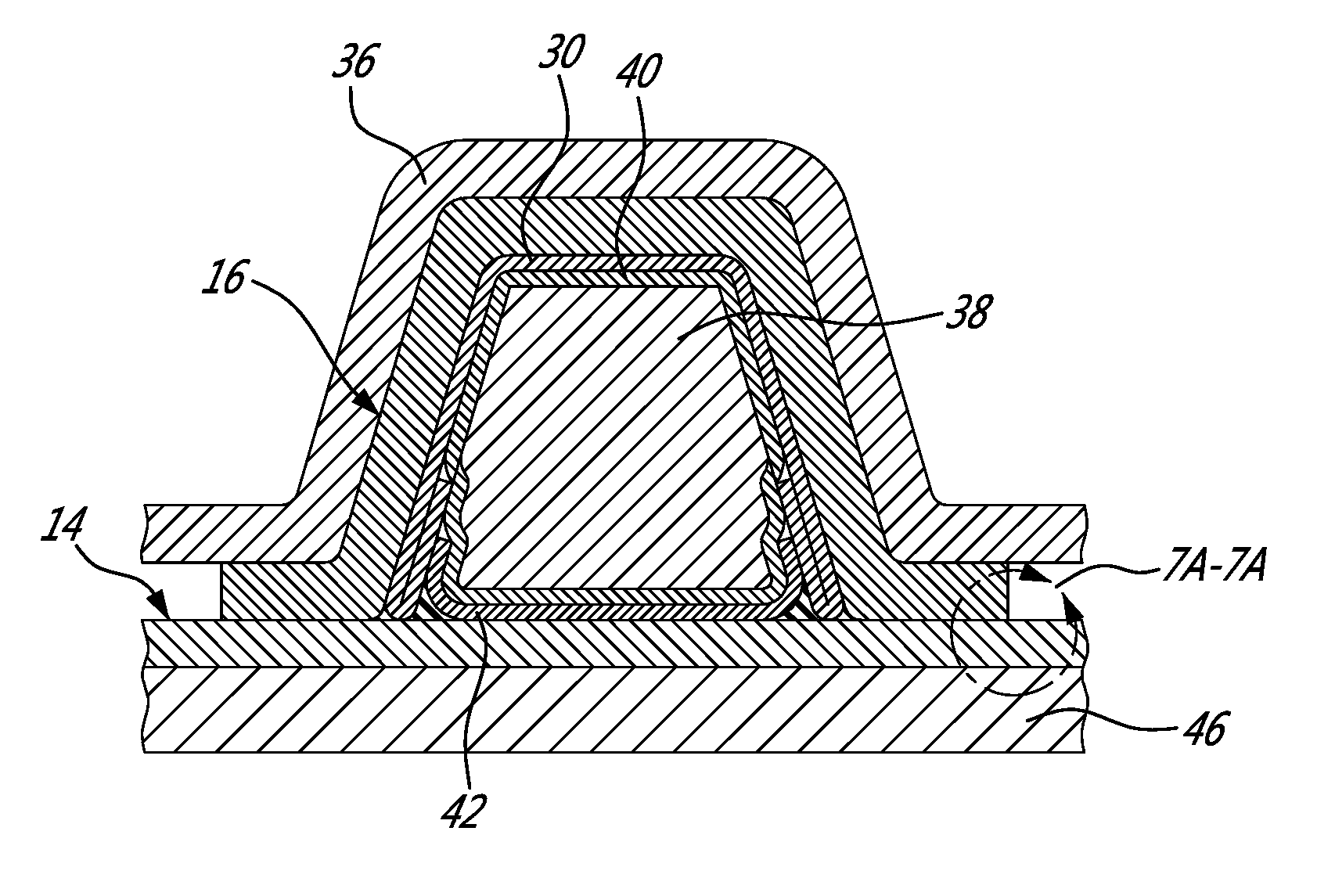
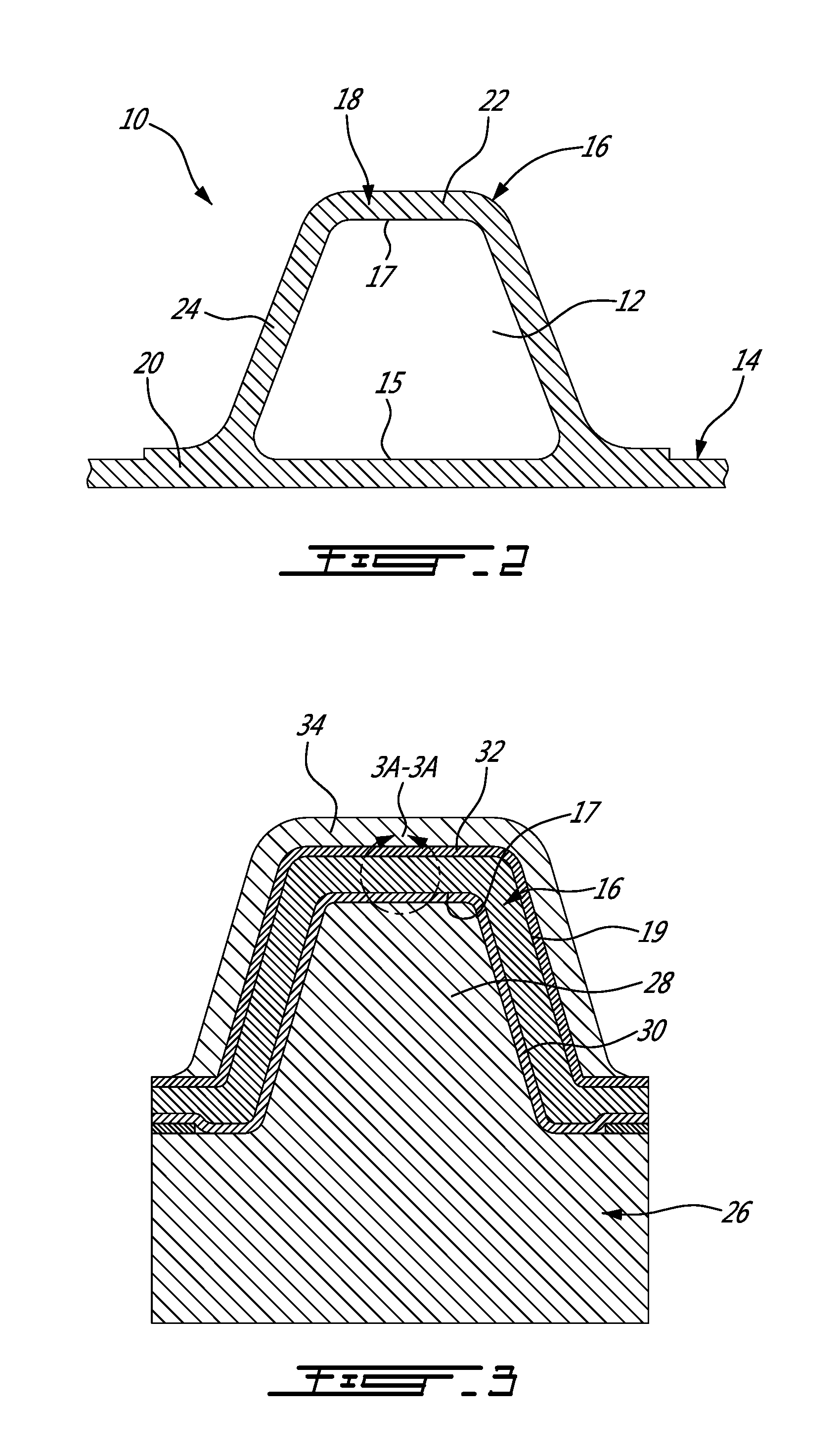
[0035]Referring to FIG. 2, a composite member 10 having a longitudinal cavity 12 defined therein,


PUM

PropertyMeasurementUnit
Lengthaaaaaaaaaa
Pressureaaaaaaaaaa
Shapeaaaaaaaaaa

Abstract

A method of preparing a composite element for forming a composite assembly having a cavity is disclosed. The method includes laying a barrier layer on a surface of the composite element which defines at least part of the cavity. A support assembly including a mandrel (38) and a film bag (40) extending on the surface of the mandrel is positioned with the film bag against the barrier layer. A sealed enclosure containing the composite element is formed through sealing engagement with the film bag. The pressure within the sealed enclosure is reduced, and the mandrel is separated from the film bag while maintaining the film bag positioned against the barrier layer. In one embodiment, the element is a stringer and is positioned against a skin. An assembly for forming a composite member is also provided.

Description


Claims


Application Information

Patent Timeline
Owner BOMBARDIER CORP
Why Eureka
Try Eureka