Image processing apparatus, method of controlling the same, and storage medium
- Summary
- Abstract
- Description
- Claims
- Application Information
AI Technical Summary
Benefits of technology
Problems solved by technology
Method used
Image

Examples
first embodiment
[0034]
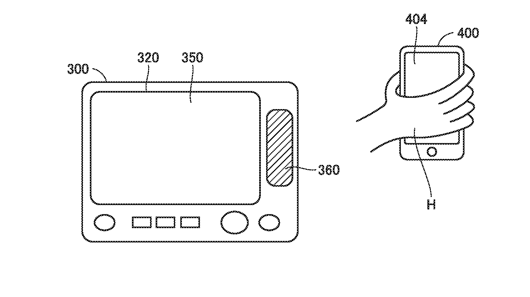
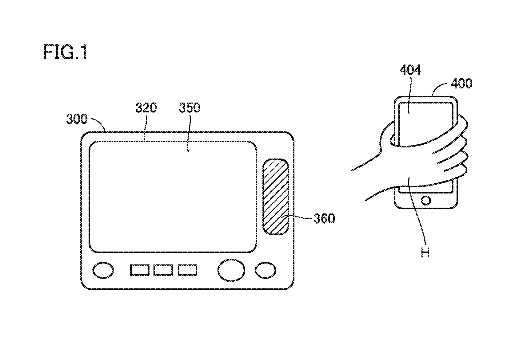
[0035]Overview of an image processing apparatus according to a first embodiment of the present disclosure will be described with reference to FIGS. 1 and 2. In the present disclosure, a multi-functional peripheral (MFP) is adopted as one embodiment of the image processing apparatus. FIGS. 1 and 2 are diagrams showing an operation panel of the MFP and a portable terminal in near field communication with the MFP according to the first embodiment.
[0036]The MFP communicates under at least two types of communication schemes. Two types of communication under the two types of communication schemes are herein distinguished from each other as “non near field radio communication” and “near field communication.”“Non near field radio communication” means communication under such a scheme as Bluetooth. “Near field communication” means radio (not wired) communication and means communication under such a scheme as NFC shorter in communication distance than “non near field radio communication.”
[
second embodiment
[0094]
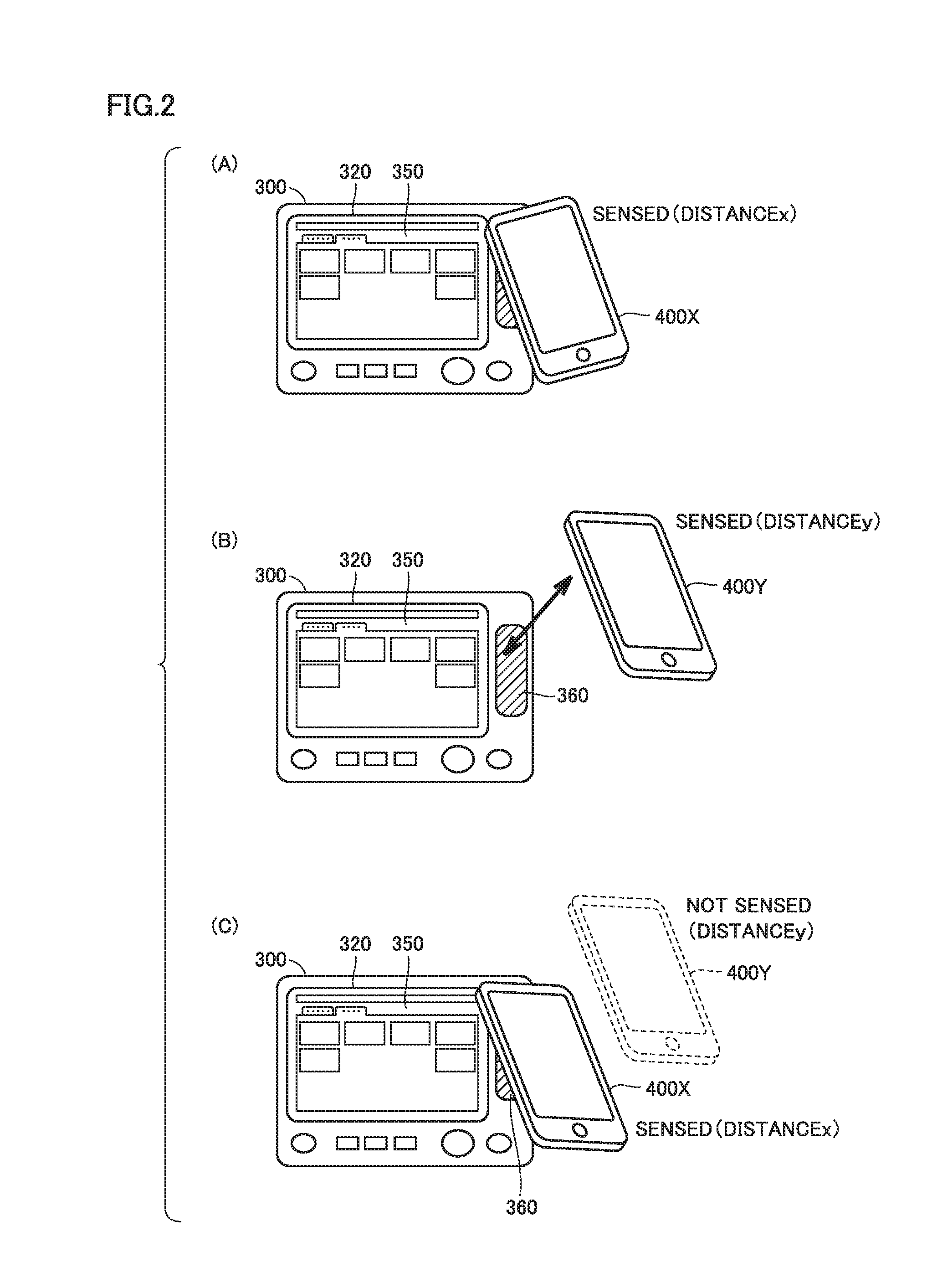
[0095]A hardware configuration of MFP 100 in a second embodiment can be the same as in the first embodiment except for a configuration specified below. In MFP 100 in the second embodiment, whether or not to establish non near field radio communication by using non near field radio communication portion 111 is determined by making use of a “sensed distance” (FIG. 8) made use of in the first embodiment and further taking into account a distance from touch area 360 to portable terminal 400 at the time when a user actually holds portable terminal 400 over touch area 360. Namely, in the second embodiment, MFP 100 corrects a distance from touch area 360 to portable terminal 400 at the time when non near field radio communication portion 111 establishes non near field radio communication based on a state of communication between portable terminal 400 and non near field radio communication portion 111 at a position where non near field radio communication with non near field radio commun
third embodiment
[0111]
[0112]A hardware configuration of MFP 100 in a third embodiment can be the same as in the first embodiment except for a configuration specified below. MFP 100 in the third embodiment determines whether or not to establish non near field radio communication by using non near field radio communication portion 111, by making use of a “sensed distance” (FIG. 8) made use of in the first embodiment and a distance from touch area 360 to portable terminal 400 at the time when a user actually holds portable terminal 400 over touch area 360. In the third embodiment, whether or not to establish non near field radio communication is determined based on a state of communication of a communication device for near field communication on the side of MFP 100 at the time when near field communication with portable terminal 400 is actually established.
[0113]
[0114]FIG. 11 is a diagram showing a functional configuration of MFP 100 in the third embodiment. As shown in FIG. 11, MFP 100 functions as sen
PUM
 Abstract
Description
Claims
Application Information
 - R&D Engineer
- R&D Manager
- IP Professional
- Industry Leading Data Capabilities
- Powerful AI technology
- Patent DNA Extraction
Browse by: Latest US Patents, China's latest patents, Technical Efficacy Thesaurus, Application Domain, Technology Topic.
© 2024 PatSnap. All rights reserved.Legal|Privacy policy|Modern Slavery Act Transparency Statement|Sitemap