Electronic card reading device

A technology of electronic cards and reading devices, applied in hybrid readers, instruments, induction record carriers, etc., can solve the problems of cost increase and inconvenience to the public, and achieve the effect of cost reduction and convenience improvement

Active Publication Date: 2020-04-07
TES TOUCH EMBEDDED SOLUTIONS (XIAMEN) INC
View PDF7 Cites 0 Cited by
  • Summary
  • Abstract
  • Description
  • Claims
  • Application Information

AI Technical Summary

Benefits of technology

This patented technology allows an electrical signal from one part called the reader's terminal (the primary) to pass through certain parts on another piece called the main or baseboard where it connectes wirelessly. These connections allow this system to communicate between different pieces of equipment like smartphones without being limited by their physical size. By connecting these two circuits together they are able to recognize and interpret digital signals more easily than traditional methods such as barcodes.

Problems solved by technology

The technical problem addressed by this patented solution relates to improving the functionality of electronic card readers that allow users to easily access multiple types of smartcards without requiring them to have separate hardware or software components like radio frequency identification (RFID).

Method used


Image

  • Electronic card reading device
  • Electronic card reading device
  • Electronic card reading device

Examples


Embodiment Construction

[0024] The preferred embodiments of the electronic card reading device according to the present invention will be described below with reference to related drawings, wherein the same components will be described with the same reference symbols.

[0025] The electronic card reading device of the present invention can be used by various types of electronic cards to identify and read digital data, thereby improving convenience in use, and at the same time saving costs for those skilled in the art in manufacturing and producing the electronic card reading device reduction. The structure and features of the electronic card reading device of the present invention will be described below with examples.

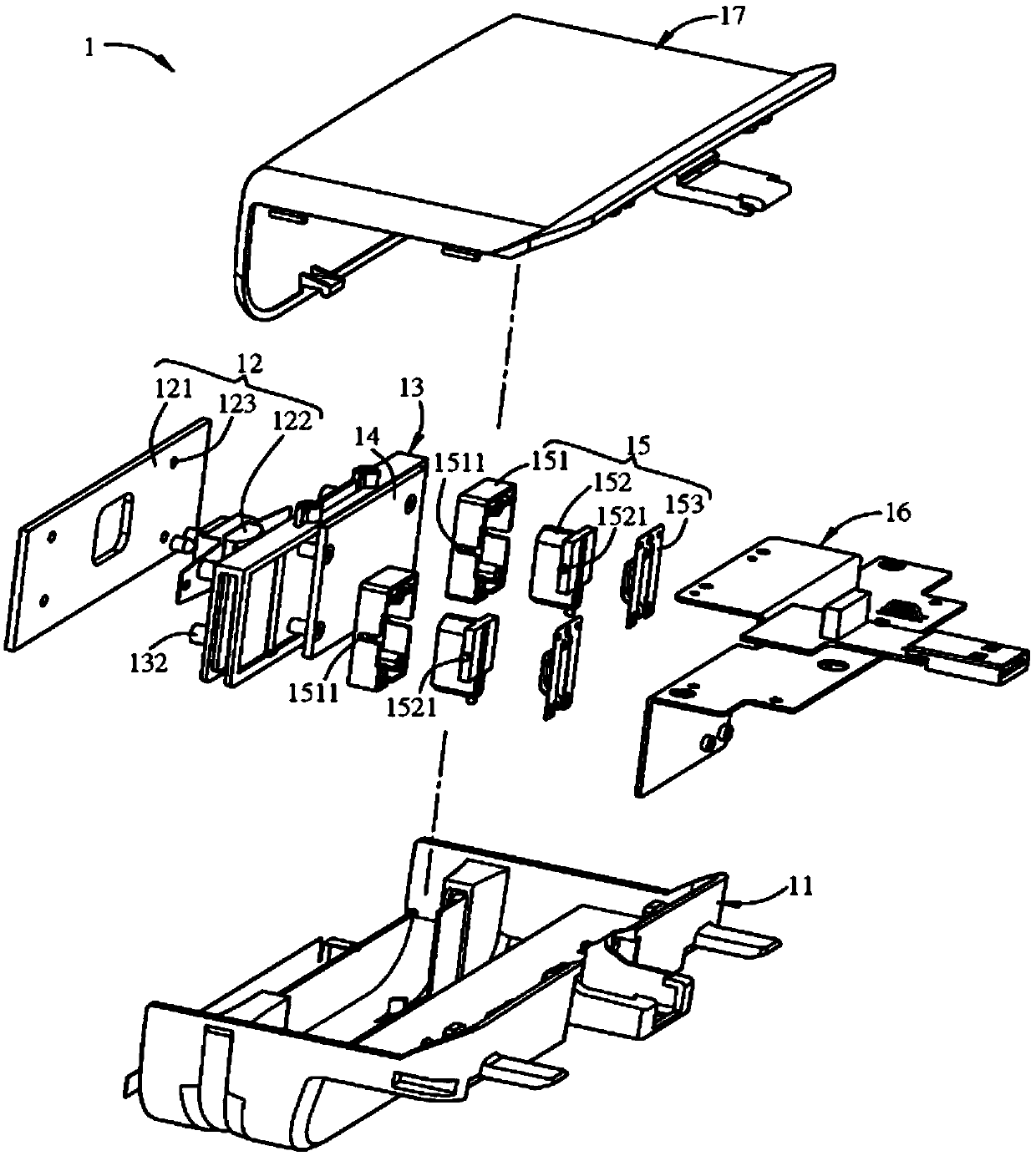
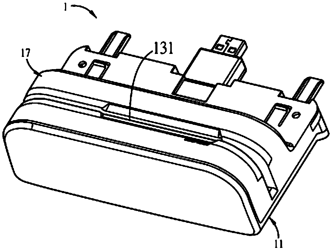
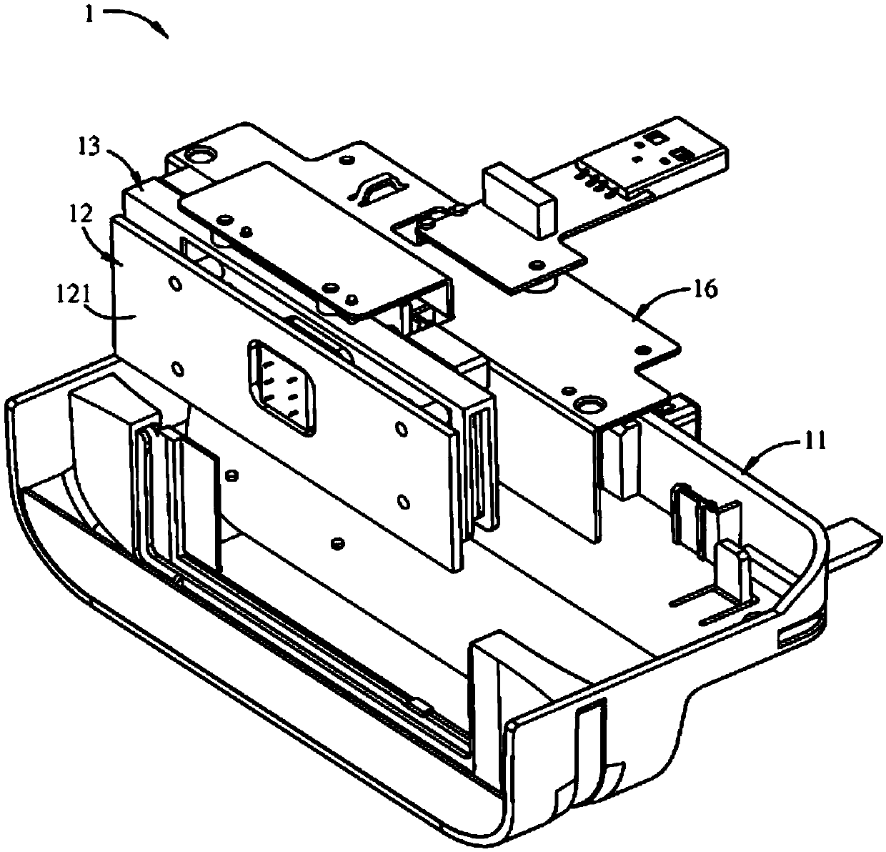
[0026] see Figure 1A to Figure 3 , which is a schematic diagram of a preferred embodiment of the electronic card reading device 1 of the present invention. The electronic card reading device 1 includes a base 11 , a first circuit board 12 , a track member 13 , and a second circuit bo


PUM


Abstract

The invention discloses an electronic card reading device. The electronic card reading device comprises a base, a first circuit board, a rail part and a second circuit board, the first circuit board is arranged on the base and comprises a near-field communication unit in non-contact inductance connection with an induction type electronic card and a magnetic stripe reading unit in inductance connection with an electronic card with a magnetic stripe. The track part is arranged adjacent to the first circuit board and comprises a card slot for an electronic card with a magnetic stripe and/or an electronic card with a chip to be movably inserted. The second circuit board is arranged adjacent to the track part and is respectively located at two opposite sides of the track part with the first circuit board, and the second circuit board is connected with the electronic card inductor with the chip.

Description


Claims


Application Information

Patent Timeline
Owner TES TOUCH EMBEDDED SOLUTIONS (XIAMEN) INC
Why Eureka
Try Eureka