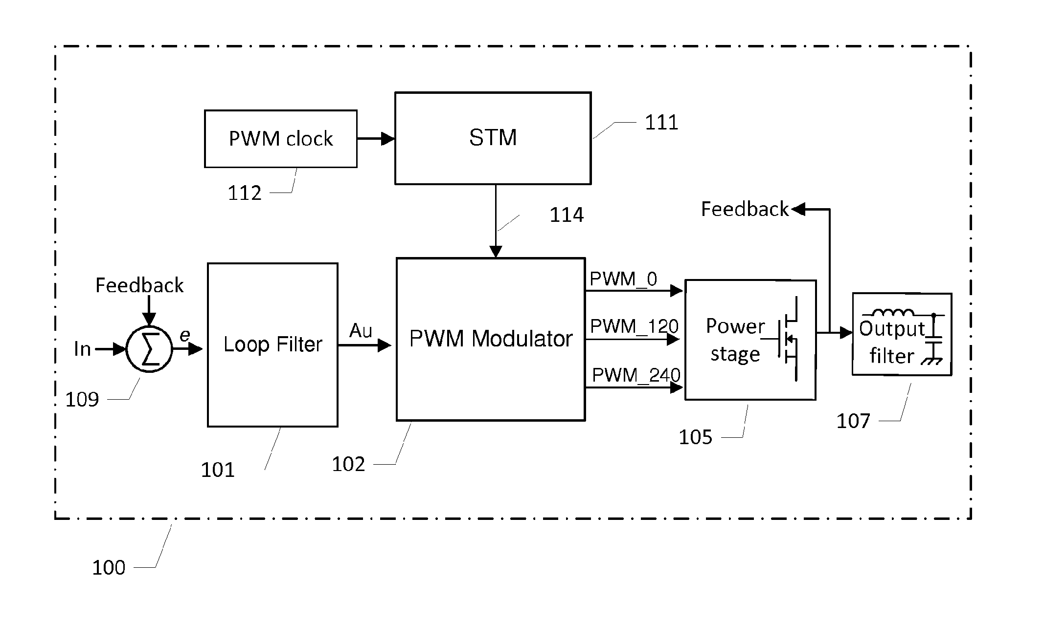
A multiphase pulse width modulator for class d audio amplifiers
- Summary
- Abstract
- Description
- Claims
- Application Information
AI Technical Summary
Benefits of technology
Problems solved by technology
Method used
Image

Examples
Example
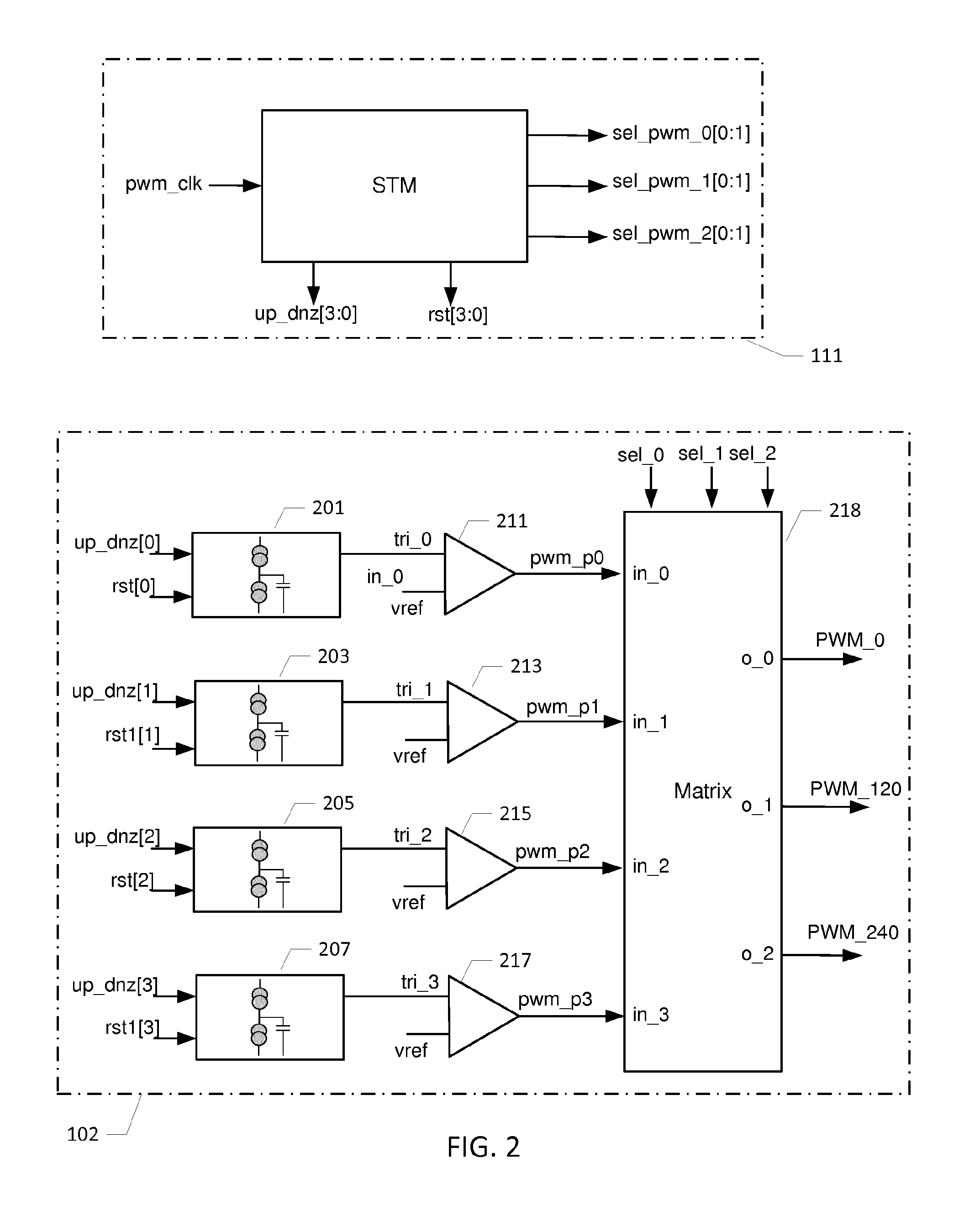
[0054]FIG. 4 is a simplified schematic diagram of a second embodiment of the multiphase pulse width modulator. Corresponding features of the first embodiment of the multiphase pulse width modulator 102, 111 and the present embodiment are indicated by corresponding reference numerals to ease comparison. The present multiphase pulse width modulator 402, 411 is configured for producing 2 mutually phase shifted pulse width modulated signals, PWM_0 and PWM_180, derived from 3 pulse width modulated phase signals supplied at the input terminals of a crosspoint or matrix switch 418, i.e. pwm_p0, pwm_p1 and pwm_p2. Hence, in the present embodiment, N equals 2. The timing of operations of the multiphase pulse width modulator 402 is controlled by a crosspoint switch controller 411 based on a state machine via a number of digital control signals up_dnz[2:0], rst[2:0], sel_pwm_0[0:1] and sel_pwm_1[0:1] similarly to the first embodiment of the modulator.
[0055]The multiphase pulse width modulator 402
Example
[0056]FIG. 6 is a simplified schematic diagram of a third embodiment of the multiphase pulse width modulator. Corresponding features of the first embodiment of the multiphase pulse width modulator 102, 111 and the present embodiment are indicated by corresponding reference numerals to ease comparison. The present multiphase pulse width modulator 602, 611 is configured for producing the four mutually phase shifted pulse width modulated signals PWM_0, PWM_90, PWM_180 and PWM_270, derived from five pulse width modulated phase signals at the input terminals of a crosspoint or matrix switch 618, i.e. pwm_p0, pwm_p1, pwm_p2, pwm_p3 and pwm_p4. Hence, in the present embodiment, N equals 4. The timing of operations of the multiphase pulse width modulator 602 is controlled by a crosspoint switch controller 611 based on a state machine via a number of digital control signals up_dnz[4:0], rst[4:0], sel_pwm_0[0:1], sel_pwm_1[0:1] , sel_pwm_2[0:1] and sel_pwm_3[0:1] similarly to the first embodimen
PUM
 Abstract
Description
Claims
Application Information
 - R&D Engineer
- R&D Manager
- IP Professional
- Industry Leading Data Capabilities
- Powerful AI technology
- Patent DNA Extraction
Browse by: Latest US Patents, China's latest patents, Technical Efficacy Thesaurus, Application Domain, Technology Topic.
© 2024 PatSnap. All rights reserved.Legal|Privacy policy|Modern Slavery Act Transparency Statement|Sitemap