Video Processing Apparatus, Control Method, and Recording Medium
a video processing and control method technology, applied in the field of video processing apparatus, control method, and recording medium, can solve problems such as difficulty for users to perform detailed operations, and achieve the effect of facilitating the operation of adjusting focus
- Summary
- Abstract
- Description
- Claims
- Application Information
AI Technical Summary
Benefits of technology
Problems solved by technology
Method used
Image

Examples
first embodiment
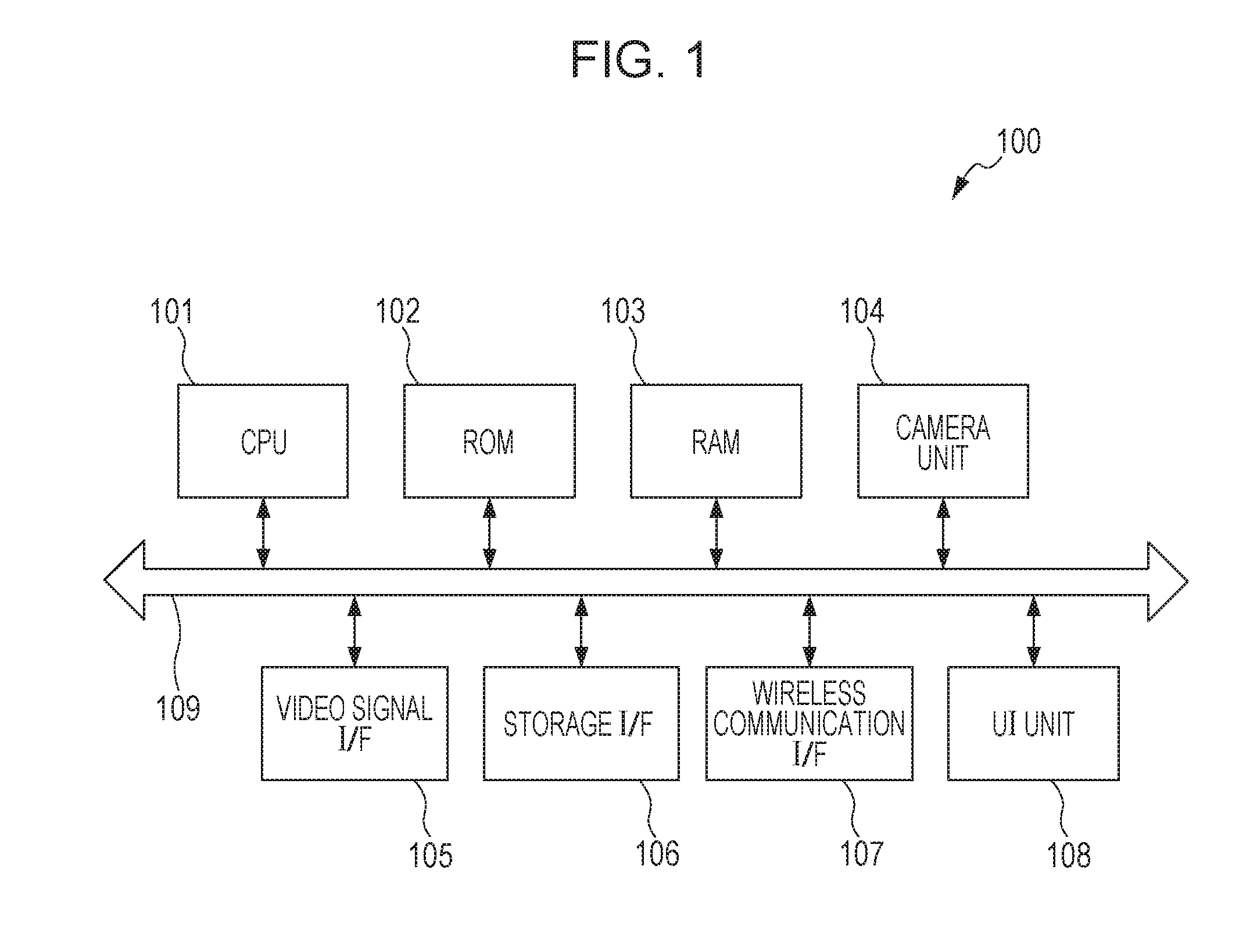
[0025]FIG. 1 is a diagram illustrating a hardware configuration of a video processing apparatus 100 according to a first embodiment. Note that, instead of the hardware configuration illustrated in FIG. 1, each block in FIG. 1 may be realized by a plurality of circuits, or a plurality of blocks may be realized by a single circuit. Although the video processing apparatus 100 of this embodiment is an imaging apparatus, the present invention is not limited to this. In FIG. 1, a CPU 101 performs a calculation, a logical determination, and the like for various processes and controls components of various units 102 to 108 connected to a bus 109. A ROM 102 stores a program for control to be performed by the CPU 101 which indicates various instructions including a processing procedure of a flowchart described below. A RAM 103 temporarily stores programs and data loaded from an external storage device (not illustrated) or the like, data externally obtained through an interface (I / F), and the l
second embodiment
[0066]The focus process performed by the video processing apparatus 100 when the single object is specified as a target of the focus process is illustrated in the first embodiment described above. In a second embodiment, a focus process performed by a video processing apparatus 100 in a case where a user specifies a plurality of objects is described.
[0067]Hereinafter, a process performed by the video processing apparatus 100 of the second embodiment will be described in detail with reference to FIG. 6 and FIGS. 7A and 7B. FIG. 6 is a flowchart illustrating an operation of performing a focus process on objects performed by the video processing apparatus 100 according to this embodiment. Furthermore, FIGS. 7A and 7B are diagrams illustrating a display screen of an UI unit 108 of the video processing apparatus 100 in a case where the video processing apparatus 100 performs the focus process on the objects.
[0068]First, a process performed by the video processing apparatus 100 will be descr
third embodiment
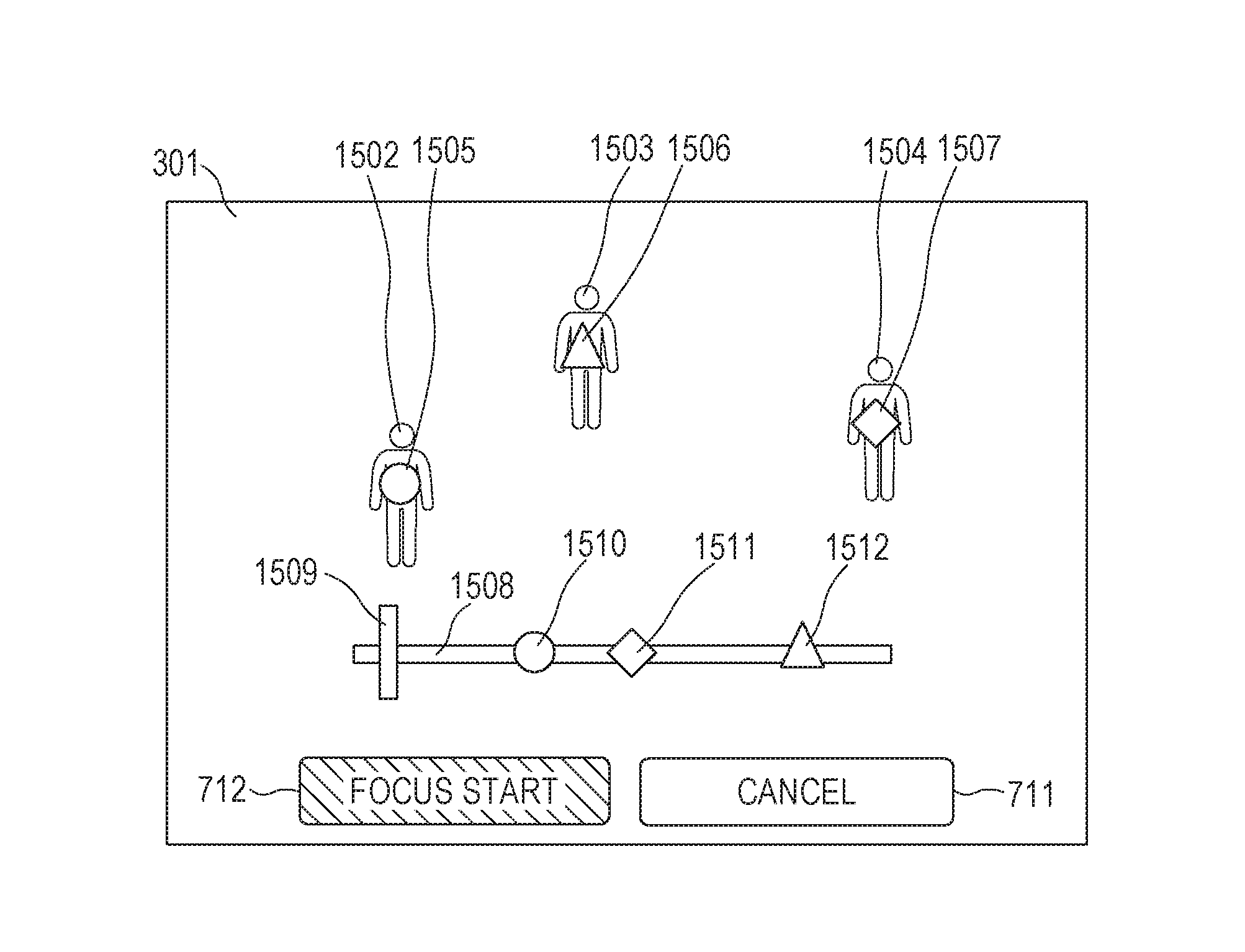
[0081]In the second embodiment described above, the video processing apparatus 100 performs the MF process by arranging the in-focus marks 715 to 717 corresponding to the plurality of objects on the single slide bar 713 as illustrated in FIG. 7B. In a third embodiment, a video processing apparatus 100 displays in-focus marks corresponding to a plurality of objects specified by a user in positions based on positions of the objects on a display screen 301 as illustrated in FIG. 9.
[0082]Hereinafter, a process performed by the video processing apparatus 100 of the third embodiment will be described in detail with reference to FIGS. 8 and 9. FIG. 8 is a flowchart illustrating an operation of performing a focus process on objects performed by the video processing apparatus 100 according to the third embodiment. Furthermore, FIG. 9 is a diagram illustrating the display screen 301 in a display unit of an UI unit 108 of the video processing apparatus 100 in a case where the video processing app
PUM
 Abstract
Description
Claims
Application Information
 - R&D Engineer
- R&D Manager
- IP Professional
- Industry Leading Data Capabilities
- Powerful AI technology
- Patent DNA Extraction
Browse by: Latest US Patents, China's latest patents, Technical Efficacy Thesaurus, Application Domain, Technology Topic.
© 2024 PatSnap. All rights reserved.Legal|Privacy policy|Modern Slavery Act Transparency Statement|Sitemap